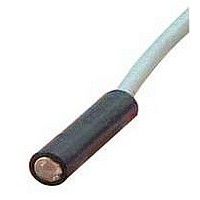
LR250 BANNER ENGINEERING, LR250 Datasheet

LR250
Manufacturer Part Number
LR250
Description
Photoelectric Sensor
Manufacturer
BANNER ENGINEERING
Datasheet
1.LR250.pdf
(2 pages)
Specifications of LR250
Output Current
250mA
Sensing Range Max
24.38m
Leaded Process Compatible
No
Peak Reflow Compatible (260 C)
No
Switch Terminals
Cable
Sensor Input
Optical
Sensing Mode
Opposed
Available stocks
Company
Part Number
Manufacturer
Quantity
Price
Part Number:
LR2501
Manufacturer:
POLYFET
Quantity:
20 000
Printed in USA
LR250 & PT250
MAXIMUM SENSOR LEAD LENGTH: 100 feet (30m) maximum;
The LR250 emitter and PT250 receiver are compact, totally-encapsulated opposed mode remote sensors whose 1/4" diameter smooth
barrel design and excellent operating characteristics make them ideal for many sensing applications. Mounting and alignment are
extremely simple, due to these sensors' wide field of view. The LR250 and PT250 may be mounted through a 1/4" (6,4mm) clearance
hole and held in place by a setscrew, or in a model SMB250 mounting block.
LR/PT250 series sensors are fully encapsulated, and have hermetically sealed lenses to eliminate internal condensation. Units may
be washed down without damage. Identical optical performance in different housing styles is available in models LR/PT200, 300, and
400 (see Banner product catalog).
The minimum object size required to break the beam of the LR250/PT250 opposed mode sensor pair is 1/8-inch. These sensors are
designed for use with Banner MICRO-AMP
modulated amplifiers, and MB Series amplifiers.
Hookup to MB Series Amplifiers
Banner remote sensors will connect to any MB Series amplifier. The model
MRB chassis (shown) has octal sockets for the amplifier and a BR-2 relay
(supplied) and provides power for the sensors and amplifier. Up to four sen-
sor pairs may be connected to one amplifier for light-operated OR or dark
operated AND operation. In multiple-sensor hookups, receivers are wired
in parallel and emitters are connected in series (see example for CM Series
modules, next page).
Several MB Series amplifiers are available. Each provides a different output
logic function. Chassis models with additional octal sockets are also avail-
able. Other types of output devices, including solid state relays, may be
ordered (see Banner catalog).
Specifications, MB Series Amplifiers
OUTPUT CONFIGURATION: open collector NPN transistor; maximum
on-state current 250mA, maximum off-state leakage current 100 micro-
RESPONSE SPEED: 1 millisecond ON and OFF.
OPERATING TEMPERATURE RANGE: 0 to +50°C (+32 to +122° F).
POWER SUPPLY REQUIREMENT: 12-18V dc at less than 100mA,
exclusive of load.
use separate shielded cables for emitter and reciever.
RANGE: up to 8 feet in opposed mode (see gain curve)
EFFECTIVE BEAM: 0.14 inch (3.6 mm) diameter
RESPONSE SPEED: a function of the amplifier (see below)
OPERATING TEMPERATURE: -40 to +100° C (-40 to +212° F)
EMITTER CHARACTERISTICS (LR250):
880nm
CONSTRUCTION: totally encapsulated, hermetically sealed lenses.
Delrin
CABLE: sensors are supplied with 6' of PVC-covered cable.
30' cables are available by special order.
Specifications, LR250 & PT250
®
housing; NEMA 1, 3, 4, 12, and 13.
®
system MA3-4 and MA3-4P modulated amplifiers, MAXI-AMP™ system CM Series
infrared LED,
Opposed Mode
Remote Sensor Pair
Wiring rules:
1) Avoid running remote sensor cables in wireways together with
power-carrying conductors.
2) Avoid running remote sensor cables through areas of known ex-
treme electrical interference (electrical "noise").
3) Always use shielded cables and only connect the shield ("drain")
wire at the amplifier.
4) When splicing, never combine emitter and receiver wires into a
common cable. (The result will be electrical "crosstalk" within the
cable, which causes a "lock-on" condition of the amplifier.)
EXCESS GAIN CURVE
BEAM PATTERN
P/N 03389C4B
Related parts for LR250
LR250 Summary of contents
Page 1
... Mounting and alignment are extremely simple, due to these sensors' wide field of view. The LR250 and PT250 may be mounted through a 1/4" (6,4mm) clearance hole and held in place by a setscrew model SMB250 mounting block. ...
Page 2
... ANSI machine safety standards for point-of-operation guarding devices. No other Banner sensors or controls are designed to meet these standards, and they must NOT be used as sensing devices for personnel protection. Banner Engineering Corporation 9714 10th Ave. No., Minneapolis, MN 55441 sees "light") or dark-operated AND logic (input to module occurs when all receivers simultaneously see " ...


