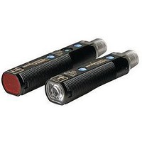
S51-PA-5-A00-NK IDEC, S51-PA-5-A00-NK Datasheet - Page 23

S51-PA-5-A00-NK
Manufacturer Part Number
S51-PA-5-A00-NK
Description
Photoelectric Sensor
Manufacturer
IDEC
Datasheet
1.95ACC1380.pdf
(26 pages)
Specifications of S51-PA-5-A00-NK
Output Current
100mA
Sensor Output
NPN
Supply Voltage Range Dc
10V To 30V
Sensor Housing
Cylinder Rotatable
Sensing Range Min
0.1m
Sensor Input
Optical
Sensing Range Max
4m
Switch Terminals
Connector
Lead Free Status / RoHS Status
Lead free / RoHS Compliant
234
A slit attachment is available to modify the beam size of through-beam sensors.
This option is recommended for detecting very small objects (near the size of the
smallest object which a sensor can detect) or for eliminating light interference
when sensors are mounted in close proximity.
Retro-refl ective
light beam is refl ected on the
receiver due to a prismatic
refl ector; an object is detected
when it interrupts the beam.
Compared to the through-beam
optic function, the signal
difference is reduced (when the
light is freely refl ected by the
refl ector and when an object
interrupts the beam) so Excess Gain is reduced and maximum operating
distances can reach 12 meters. It is necessary to operate in clean environments
without dirt or dust. A retro-refl ective sensor typically operates in the dark mode:
output is activated when an object interrupts the light beam between the sensor
and refl ector.
When installing sensors which detect refl ected light, make sure that unwanted
light refl ections from nearby surfaces, such as the fl oor, walls, refl ective machin-
ery or stainless steel, do not reach the optical receiver.
Also, make sure that refl ected-light sensors mounted in close proximity do not
cause interfering refl ections. When it is not possible to maintain the recommend-
ed clearance between sensors, as noted in the individual installation sections,
provide light barriers between sensors.
Prismatic Refl ector
A prismatic refl ector is able to refl ect incident light in a parallel manner, with a
refl ection coeffi cient higher than any other object for angles less than 15°. Typi-
cally the operating distance proportionally increases according to the refl ector’s
dimensions. The refl ector can rotate the incident light’s polarization plane at 90°.
Polarized Retro-refl ective
sion light is polarized on a vertical plane, while the reception is obtained only
through a polarized fi lter on a horizontal plane. A prismatic refl ector rotates the
light plane at a right angle, while the light refl ected from the object maintains
polarization plane unvaried and is blocked by the fi lter placed on the receiver.
Consequently, only the light refl ected by the prismatic refl ector is received.
Photoelectric sensors with this function contain both the emitter and
receiver inside the same
housing. The emitted
In presence of critical detection of objects with very refl ective surfaces,
such as shiny metals or mirrored glass, retrorefl ex sensors with polar-
ized fi lters have to be used. In polarized retrorefl ex sensors, the emis-
Retro-refl ection
with prismatic
refl ector
General Information
Retro-refl ection
with fl at refl ective
surface
www.idec.com
Retro-refl ective for Transparent Objects
signal differences that the light undergoes when it passes through a transparent
object.
Diffuse Proximity
need of prismatic refl ectors. Proximity
sensors represent the most economic
and fastest mounting solution.
However, they work with weaker
signals compared to retro-refl ective
sensors. Excess Gain is reduced and
operating distance, depending on the
object’s refl ection degree, can only
reach 2 meters.
A proximity sensor normally operates
in light mode: the output is activated when an object enters the detection area
and refl ects light emitted by the sensor.
Background Suppression
sensitivity, but is obtained through
optic triangulation, mechanically
acting on the lenses or photoelements
angle or electronically using PSD
(Position-Sensitive Detectors)
receiving systems. Consequently the
detection of an object is independent
of other objects behind (or in the
background), which are suppressed.
Moreover, due to this adjustment
method, all objects can be detected at
the same distance independent of
their color.
Distance Sensors
The main technologies involved are optic triangulation and time-of-fl ight. The
fi rst allows very precise measurements on short distances, while the second is
ideal for medium and long distances.
For detection of transparent objects, such as PET bottles or Mylar
sheets, a low-hysteresis retro-refl ective sensor (capable of detecting
small signal differences) can be used. These sensors detect small
Photoelectric sensors with this function contain both the emitter and
receiver inside the same housing. The emitted light beam is refl ected
on to the receiver directly by the object, which is detectedwithout the
Background suppression sensors allow the operator to precisely set the
maximum detection distance. The operating distance adjustment is not
based upon the receiver’s
Distance sensors supply an analog signal of 0-10V or 4-20mA propor-
tional to the measurement of the distance between the emitting optics
and the target.
Sensors


