E2CCR8A Omron, E2CCR8A Datasheet
E2CCR8A
Specifications of E2CCR8A


Related parts for E2CCR8A

E2CCR8A Summary of contents
Page 1
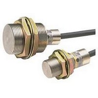
... Separate Amplifier Proximity Sensor with Adjustment Potentiometer E2C/E2C-H Separate Amplifier Sensor with Sensitivity Adjustment • Compact design with smaller Sensor Head. • Heat-resistance model available for application between −10 and 200°C. Be sure to read Safety Precautions on page 15. Ordering Information Sensors [Refer to Dimensions on page 18.] ...
Page 2
Accessories (Order Separately) Mounting Brackets [Refer to Dimension on page 21.] Name Model Y92E-F3R5 Mounting Brackets Y92E-F5R4 Connection Sockets [Refer to Dimension on page 21.] Name Model PYF08A Front Connection Sockets P2CF-08 P2CF-11 P3G-08 Back Connection Sockets P3GA-11 Adapters [Refer ...
Page 3
Ratings and Specifications Standard Models Sensors Model E2C-CR8A/ -CR8B Item Sensing distance 1.8 mm (at 23°C) Ambient Stable 0 to 0.8 mm temperature sensing area 40° 1.2 mm Differential travel Refer to Ratings and Specifications ...
Page 4
... Sensing distance 20% min. of rated sensing distance with 4- adjustment range *2 turn potentiometer Differential travel Differential travel fixed (10% max. of sensing distance) adjustment range Solid- Re- (Refer to the response frequency of the Proximity Sensor.) state sponse time Relay NPN PNP Load resistance: 4.7 Load resistance: 4.7 kΩ ...
Page 5
Model E2C-GE4A Item 2 Shock resistance Destruction: 100 m/s 3 times each and Z directions Life expectancy Connection method Terminal block Weight (packed Approx state) *4 Accessories Instruction manual *1. A full-wave rectification power supply ...
Page 6
Cable Lengths for Sensor-Amplifier Unit Combinations Standard Models Sensor E2C-CR8A E2C-CR8B Amplifier Units E2C-GE4A E2C-GF4A E2C-WH4A Set cable length switch to desired position. E2C-JC4AP E2C-JC4A E2C-AM4A Set cable length switch to desired position. E2C-AK4A Note: The standard cable length is ...
Page 7
Engineering Data (Typical) Sensing Area E2C-CR8@ 1 1.4 Sensing distance (variable): 0.16 to 0.8 mm 1.2 1.0 100% 0.8 0.6 50% 0.4 20% 0.2 −3 −2 − Sensing Head Distance Y (mm) E2C-X1A/-C1A 1.6 ...
Page 8
Influence of Sensing Object Size and Material E2C-CR8@ 1.6 d × 1.4 X 1.2 1.0 Iron 0.8 0.6 0.4 0 Side length of ...
Page 9
... E2C-GF4A VDC 13 Proximity 47 V Sensor 2.2 Ω main 9 circuit 100 mA 4.7 kΩ max VDC 47 V 2.2 Ω 7 Output 2 (PNP) Proximity Sensor 2.2 Ω main 8 circuit Output 1 (PNP E2C-AK4A 2.2 Ω max. 5 Proximity Sensor 47 V main circuit 6 E2C/E2C-H Brown VDC 100 mA 2.2 Ω ...
Page 10
... Applicable Socket: P2CF- 100 to 240 VAC Relay output E2C/E2C-H E2C-JC4AP Proximity Sensor Brown VDC Shield Line Black NPN open- collector output Blue 0 V Orange Self-diagnostic output Sensor cable length compensation terminals* * Sensor Cable Length Compensation These terminals can be use to switch the cable length ...
Page 11
Load Connections Model E2C-JC4A, E2C-JC4@H Load DC load • Relay • Solenoid Current-sink- ing load • Program- mable Controller • Sensor Controller Brown 4.7 k Black Voltage load (logic circuit) Blue Interface circuits Model Load DC load • Relay • ...
Page 12
Model Load DC load • Relay Amplifier Unit • Solenoid Current-sinking load (photocou- pler) Solid- • Programmable Amplifier Unit state Controller load • Sensor Controller * For a current-sourcing load, connect to the negative side of the transistor/photocoupler output. Voltage ...
Page 13
E2C-JC4AP Mounting screw Cable length compensation terminals Operation mode selector Detection Stability indicator indicator (green) (red) Sensing distance adjuster Operation Timer switch switch Changes ON NO/NC. OFF: No delay E2C-WH4A Cable length compensation switch Switched between 3 and ...
Page 14
Operation switch Changes NO/NC. Cable length compensation switch* Differential travel adjuster * Cable Length Compensation Switching Set this switch to the proper setting depending on whether the standard cable length is being used or the cable has been cut shorter. ...
Page 15
Safety Precautions Refer to Warranty and Limitations of Liability. WARNING This product is not designed or rated for ensuring safety of persons either directly or indirectly. Do not use it for such purposes. Precautions for Correct Use Do not use ...
Page 16
Mounting Mounting the Amplifier Unit E2C-JC4A, E2C-JC4@H Lengthwise Mounting (1)Secure the Mounting Bracket with the enclosed M3 screws. (2)Slide the protrusion on the Amplifier Unit into the holes on the Mounting Bracket. (3)Secure the Amplifier Unit with mounting screws. ...
Page 17
E2C-A@4A Using P2CF-11, P2CF-08 When aligning the Amplifier Unit vertically with the Socket, consider the space required for the hooks and allow a leeway of about 20 mm above and below the Amplifier Unit. Hook Duct or other object P2CF-11 ...
Page 18
Dimensions Main Units Sensor E2C-CR8A/-CR8B 3.5 dia 3.5 dia. 2.5-dia. coaxial cable (50 Ω) with 1 conductor (Conductor cross section: 0.14 mm Standard length *E2C-CR8B: Diameter is 3.8. E2C-X1A 9.7 dia × ...
Page 19
Amplifier Units E2C-GE4A E2C-GF4A 27.2 E2C-AK4A (11-pin) E2C-AM4A (8-pin) Detection indicator (red) E2C-JC4A Mounting Bracket Installation M2.6 14 Two, 3.3 dia. 3 (4) R1.65 3.3 E2C-JC4AP Mounting Bracket Installation Detection indicator (red) M2.6 (10) Two. ...
Page 20
E2C-JC4@H Two, 3.3 dia 2.5 *1. After completing adjustments, attach the caution label to prevent adjustment mistakes *2. Not required when mounting to DIN Track. *3. 4-dia. vinyl-insulated round cable with 3 conductors (Conductor cross section: ...
Page 21
Accessories (Order Separately) Mounting Bracket Mounting Bracket (for Unthreaded Cylindrical Models) Y92E-F3R5 (for 3.5 dia.) Y92E--F5R4 (for 5.4 dia.) Front Connection Sockets PYF08A Two, 4.2 × 5 mounting holes 72 max. 23 max. P2CF-08 Eight, M3.5 × 7.5 Sems screws ...
Page 22
Back Connection Sockets P3G-08 45 P3GA-11 45 Embedded Mounting Adapter (for E2C-AK4A/E2C-AM4A Amplifier Unit) Y92F-30 58 Y92F-70 88 45± 0.15 45± Y92F-71 58 45± 0.2 Terminal Arrangement and 27 dia. Internal Connections (Bottom View 4.9 Terminal Arrangement and ...
Page 23
... Please read and understand this catalog before purchasing the products. Please consult your OMRON representative if you have any questions or comments. WARRANTY OMRON's exclusive warranty is that the products are free from defects in materials and workmanship for a period of one year (or other period if specified) from date of sale by OMRON. OMRON MAKES NO WARRANTY OR REPRESENTATION, EXPRESS OR IMPLIED, REGARDING NON-INFRINGEMENT, MERCHANTABILITY, OR FITNESS FOR PARTICULAR PURPOSE OF THE PRODUCTS ...