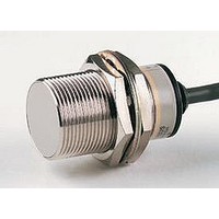
E2EX2D1M1 Omron, E2EX2D1M1 Datasheet

E2EX2D1M1
Specifications of E2EX2D1M1
Related parts for E2EX2D1M1
E2EX2D1M1 Summary of contents
Page 1
... M30 No Unshielded M8 M12 M18 M30 Note different oscillating frequency is available. Add a “5” to the part number (e.g., E2E-X3D15-N E2E sensors with robotic cable are available. Add a “-R” in the part number (e.g., E2E-X3D1-R). F-2 For more Information: U.S. www.sensors.omron.com Sensing distance ...
Page 2
... Note different oscillating frequency is available. Add a “5” to the part number (e.g., E2E-X3D15-N E2E sensors with a “G” in the part number denotes alternate pin arrangement. Refer to the Connections section. ® Connector cordsets: For MicroChange For more Information: U.S. www.sensors.omron.com Size Sensing distance M12 ...
Page 3
... M30 M8 M12 Unshielded M18 M30 Accessories Description Mounting brackets Silicone rubber covers for shielded sensors Connector cordsets Note: Use OMRON Y96E-44@D@ cordsets with M12 connector; use XS3F cordsets with M8 connector. F-4 For more Information: U.S. www.sensors.omron.com Sensing distance Sensing distance 2 mm ...
Page 4
... IEC IP67 Enclosure rating NEMA 12, 13 Body Stainless steel Material Sensing PBT face For more Information: U.S. www.sensors.omron.com Fits M8 size sensors Fits M12 size sensors Fits M18 size sensors Fits M30 size sensors E2E-X8MD@ E2E-X7D@ M12 M18 Shielded Unshielded Shielded 3 mm ...
Page 5
... Dimensions Unit: mm (inch) Prewired Models (Shielded) Fig. 1: E2E-X2D@ Fig. 3: E2E-X3D@ F-6 For more Information: U.S. www.sensors.omron.com E2E-X@D1-M1J-T No Polarity Note The load can be connected to either the +V or 0-V side The E2E-X@D1-M1J-T has no polarity. Therefore, terminals 3 and 4 have no polarity. Prewired Models (Unshielded) Fig. 2: Fig ...
Page 6
... Prewired Models (Shielded) Fig. 5: E2E-X7D@ Fig. 7: E2E-X10D@ Connector Models (Shielded) Fig. 9: E2E-X2D@-M1G Fig. 11: E2E-X3D@-M1G Fig. 13: E2E-X7D@-M1G For more Information: U.S. www.sensors.omron.com Prewired Models (Unshielded) Fig. 6: E2E-X14MD@ Fig. 8: E2E-X20MD@ Connector Models (Unshielded) Fig. 10: E2E-X4MD@-M1G Fig. 12: E2E-X8MD@-M1G Fig. 14: E2E-X14MD@-M1G Canada www ...
Page 7
... Unit: mm (inch) Fig. 15: E2E-X10D@-M1G M8 Connector Models (Shielded) Fig. 17: E2E-X2D@-M3G F-8 For more Information: U.S. www.sensors.omron.com Fig. 16: E2E-X20MD@-M1G M8 Connector Models (Unshielded) Fig. 18: E2E-X4MD@-M3G Canada www.sensors.omron.ca ...
Page 8
... No ® Change NC E2E-X@D2-M3G Note: Pin arrangements conform to IEC standards. For more Information: U.S. www.sensors.omron.com Pin arrangement Note: Terminals 2 and 3 are not used. Note Terminals 1 and 2 are not used Terminals 3 and 4 have no polarity. Note: Terminals 1 and 2 are not used. Note: Terminals 3 and 4 are not used. ...
Page 9
... Cancellation; Etc. Orders are not subject to rescheduling or cancellation unless Buyer indemnifies Omron against all related costs or expenses. 10. Force Majeure. Omron shall not be liable for any delay or failure in delivery resulting from causes beyond its control, including earthquakes, fires, floods, strikes or other labor disputes, shortage of labor or materials, accidents to machinery, acts of sabotage, riots, delay in or lack of transportation or the requirements of any government authority ...
Page 10
... Complete “Terms and Conditions of Sale” for product purchase and use are on Omron’s website at www.omron.com/oei – under the “About Us” tab, in the Legal Matters section. ALL DIMENSIONS SHOWN ARE IN MILLIMETERS. To convert millimeters into inches, multiply by 0.03937. To convert grams into ounces, multiply by 0.03527. ...


