S18UUA BANNER ENGINEERING, S18UUA Datasheet - Page 4
S18UUA
Manufacturer Part Number
S18UUA
Description
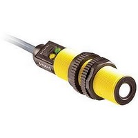
Ultrasonic Sensor
Manufacturer
BANNER ENGINEERING
Type
Ultrasonicr
Specifications of S18UUA
Sensing Range Min
30mm
Sensing Range Max
300mm
Switching Frequency
300kHz
External Diameter
18mm
Operating Temperature Range
-20°C To +60°C
Supply Voltage
30VDC
Frequency
300kHz
Brand/series
S18U
Current, Switching
65 mA
Function
Proximity
Ip Rating
IP67
Mounting Type
Threaded
Output
Voltage
Primary Type
Proximity
Range, Measurement
300 mm
Technology
Ultrasonic
Termination
Cable
Voltage, Supply
30 VDC
Voltage, Switching
10 VDC
Accessories Available
Cordsets, Brackets and Waveguides
Body Material
Thermoplastic Polyester
Contact Rating
65 MA
Lead Free Status / Rohs Status
RoHS Exempt Product


General Notes on Programming
• The sensor will return to Run mode if the first Teach condition is not registered
• After the first limit is taught, the sensor will remain in Program mode until the Teach
• To exit Program mode without saving any changes, press and hold the programming
The U-GAGE S18U sensor may be programmed for either a positive or a negative
output slope, based on which limit is taught first (see Figure 3). If the Near limit is
taught first, the slope will be positive. If the Far limit is taught first, the slope will be
negative. Banner’s scalable output automatically distributes the output signal over the
width of the programmed sensing window.
In the event of signal loss, the analog output goes to 3.6 mA or 0V dc, which may be
used to trigger an alarm.
U-GAGE
4
within 120 seconds.
sequence is finished.
push button > 2 seconds (before teaching the second limit). The sensor will revert to
the last saved limits.
P/N 110738 rev. A
• Push and hold the
• Position the target for
• “Click” the push button
• Position the target for
• “Click” the push button
...
...
™
push button
the first limit
the second limit
Teaching Minimum and Maximum Limits
S18U Series Sensor — Analog Output
0.04 < “click” < 0.8 sec.
...
...
Push Button
Analog Output Slope:
D
D
...
...
Procedure
• No action required; sensor is ready for
• Position the target for the first limit
• Single-pulse the remote line
• Position the target for the second limit
• Single-pulse the remote line
1st limit teach
D
0.04 sec. < T < 0.8 sec.
or
or
Remote Wire
T
T
T
T
or
Banner Engineering Corp.
www.bannerengineering.com • Tel: 763.544.3164
Figure 3. Analog output slope
Output LED: ON Red
Power LED: ON Green (good signal) or
Power LED: Must be ON Green
Output LED: Flashing Red
Output LED: ON Red
Power LED: Must be ON Green
Output LED: Yellow or OFF
Output LED: Flashing Red
(Sensor learns the 10V dc or 20 mA limit)
(Sensor learns the 0V dc or 4 mA limit)
20
10
4
0
T
T
T
T
T
T
T
T
T
T
T
T
ON Red (no signal)
Window
Window
Teach Unacceptable
Teach Unacceptable
Near
T
T
Near
T
T
T
T
Current-Sourcing Models
Voltage-Sourcing Models
Teach Accepted
Teach Accepted
T
T
T
T
Target Position
Result
•
Target Position
Minneapolis, MN U.S.A.
T
T
Positive
Positive
T
T
Slope
Slope
Window
Window
T
T
Far
Far
T
T
T
T
T
T
T
T
Related parts for S18UUA
Image
Part Number
Description
Manufacturer
Datasheet
Request
R

Part Number:
Description:
Photoelectric Sensor
Manufacturer:
BANNER ENGINEERING
Datasheet:

Part Number:
Description:
Photoelectric Sensor
Manufacturer:
BANNER ENGINEERING
Datasheet:

Part Number:
Description:
LEDIR70XD4-XM-81039 MAX INTENS STROBE ONLY NO BANNER MARKS
Manufacturer:
BANNER ENGINEERING
Part Number:
Description:
M18SP6DL-72225 LABELED MOELLER NO BANNER MARKINGS BULK PACK
Manufacturer:
BANNER ENGINEERING
Part Number:
Description:
M18SP6DLQ-72226 LABLED MOELLER NO BANNER MARKINGS BULK PACK
Manufacturer:
BANNER ENGINEERING
Part Number:
Description:
M18SP6L-72223 LABELED MOELLER NO BANNER MARKINGS BULK PACK
Manufacturer:
BANNER ENGINEERING
Part Number:
Description:
M18SP6LQ-72224 LABELED MOELLER NO BANNER MARKINGS BULK PACK
Manufacturer:
BANNER ENGINEERING
Part Number:
Description:
P4D1-77908 P4 DRIVER GENERIC NO BANNER MARKINGS RESALE TO CUSTOMER
Manufacturer:
BANNER ENGINEERING
Part Number:
Description:
Photoelectric Sensor
Manufacturer:
BANNER ENGINEERING
Datasheet:

Part Number:
Description:
Programmable Indicator Light
Manufacturer:
BANNER ENGINEERING
Datasheet:
Part Number:
Description:
INDICATOR LED PANEL 50MM GRN/RED/YEL 30V
Manufacturer:
BANNER ENGINEERING
Datasheet:
Part Number:
Description:
Programmable Indicator Light
Manufacturer:
BANNER ENGINEERING
Datasheet: