XCMD2110L1 SQUARE D, XCMD2110L1 Datasheet - Page 202
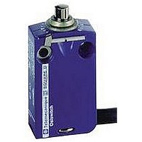
XCMD2110L1
Manufacturer Part Number
XCMD2110L1
Description
LIMIT SWITCH, 1NO.1NC, 240VAC, 250VDC, 6A
Manufacturer
SQUARE D
Datasheet
1.XCKD2102N12.pdf
(246 pages)
Specifications of XCMD2110L1
Actuator Style
Top Plunger
Operating Force Max
0.06N
Switch Operation
(ON)
Contact Voltage Ac Max
240V
Contact Voltage Dc Max
250V
Contact Current Ac Max
6A
Contact Current Dc Max
6A
Lead Free Status / RoHS Status
Contains lead / RoHS non-compliant


Limit Switches
9007C Heavy Duty Industrial—Non-Plug-in Body, Metal
Hazardous Location
202
3
1
4
3
2
1
4
3
2
1
4
3
2
1
Type of head
Hazardous location
non-plug-in body type
Type of operator
Type of direction
Catalog numbers
1 N.O. 1 N.C. snap action
2 N.O. 2 N.C. snap action
2 N.O. 2 N.C. snap action
Neutral position
2 N.O. 2 N.C. two stage
snap action
Weight, kg (lb)
Contact operation
Characteristics (nominal operating data)
Switch actuation
Type of actuation
Pre-travel
Pre-travel two stage
First stage
First stage to second stage
Total travel
Differential
Reverse overtravel
Operating torque/force
1 pole & 2 pole
Terminal wire sizes
(Cabling/Screw Clamp)
Repeatability
(linear travel of cam)
Cable entry
1.
2.
Mode of operation of the lever arm is easily convertible to clockwise or both.
Simply pull out and rotate the arrow to the letters representing the desired direction—CW, CCW, or CW/CCW.
Dimensions:
pages 204 and 205
Lever arm type must be ordered separately from page 190 to 193.
These devices are factory set to operate the contacts in both the CW and CCW directions. Mode of operation is field convertible to CW
only or CCW only.
To order factory converted devices: For CCW only operation, change the 2 at the end of the Type number to 1 (for example: C54B2
becomes C54B1). For CW only operation, delete the 2 at the end of the Type number (for example, C54B2 becomes C54B).
© 1997–2007 Schneider Electric All Rights Reserved
4
2
8
7
6
5
8
7
6
5
8
7
6
5
Rotary (lever arm type) (1)
Standard pre-travel
spring return
CW & CCW (2)
9007CR53B2
9007CR61B2
9007CR65B2
1.020 (2.25)
By 30° cam
10°
10°
2.5°
90°
4°
90°
4 lb-in (0.45 N•m)
1 or 2, 12–22 AWG (2.05–0.644 mm
0.05 mm (± 0.002 in. )
1/2-14 NPT standard, optional M20 x 1.5 mm for ISO cable entry
1-2
3-4
1-2
3-4
5-6
7-8
5-6
7-8
1-2
3-4
5-6
7-8
1-2
3-4
5-6
7-8
1-2
3-4
1-2
3-4
0
0
10° 12.5°
0
10°
10°
contact closed
4°
4°
4°
4°
90°
90°
90°
Low differential
spring return
CW & CCW (2)
9007CR53A2
9007CR61A2
9007CR65A2
1.020 (2.25)
5°
5°
1.5°
2°
0.03 mm (± 0.001 in.)
1-2
3-4
5-6
7-8
1-2
3-4
5-6
7-8
1-2
3-4
1-2
3-4
1-2
3-4
1-2
3-4
5-6
7-8
5-6
7-8
0
0
0
5° 6.5°
5°
5°
2°
2°
2°
2°
2
) wires maximum
90°
90°
90°
1-2
3-4
1-2
3-4
0.05 mm (± 0.002 in.)
Standard pre-travel
spring return
CW & CCW
9007CR67T10
1.020 (2.25)
10°
—
—
4°
90°CCW
CCW
4°
contact open
10° 0 10°
0
4°
90°CW
Neutral position
CW
5-6
7-8
5-6
7-8
1-2
3-4
1-2
3-4
Low differential
spring return
CW & CCW
9007CR67T5
1.020 (2.25)
5°
—
—
2°
0.05 mm (± 0.002 in.)
90°CCW
CCW
2°
5° 0 5°
0
2°
90°CW
CW
5-6
7-8
5-6
7-8
Light operating torque
spring return
CW & CCW (2)
9007CR53N2
9007CR61N2
9007CR65N2
1.020 (2.25)
10°
10°
2.5°
4°
25 oz-in (0.18 N•m)
0.05 mm (± 0.002 in.)
1-2
3-4
5-6
7-8
1-2
3-4
5-6
7-8
1-2
3-4
1-2
3-4
1-2
3-4
1-2
3-4
5-6
7-8
5-6
7-8
0
0
0
10° 12.5°
10°
10°
4°
4°
4°
4°
/
90°
90°
90°
CW (trip) CCW (reset)
9007CR53C
9007CR61C
1.020 (2.25)
45°
—
—
90°
—
—
3 lb-in (0.34 N•m)
0.05 mm (± 0.002 in.)
1-2
3-4
1-2
3-4
1-2
3-4
1-2
3-4
5-6
7-8
5-6
7-8
Maintained contact
0
0
45°
45°
03/2007
90°
90°
Related parts for XCMD2110L1
Image
Part Number
Description
Manufacturer
Datasheet
Request
R


Part Number:
Description:
Pushbutton, Non-Illum'd Red "STOP", Momentary, 1NO-1NC, Square 30mm, 10A, 600V
Manufacturer:
SQUARE D
Datasheet:

Part Number:
Description:
KITS,TWIDO? PROGRAMMABLE CONTROLLERS,KITS,TWIDOPACK STARTER KIT - ADVANCED LEVEL,PROGRAMMABLE CONTROLLERS,TWIDO? PROGRAMMABLE CONTROLLERS ,SQUARE D
Manufacturer:
SQUARE D

Part Number:
Description:
LAMPS,INDICATOR,STACKABLE,LAMPS, STACKABLE INDICATOR,VISUAL INDICATING SIGNALS,XVB SERIES INDICATING BANKS ,SQUARE D
Manufacturer:
SQUARE D
Part Number:
Description:
LAMPS,INDICATOR,STACKABLE,LAMPS, STACKABLE INDICATOR,VISUAL INDICATING SIGNALS,XVB SERIES INDICATING BANKS ,SQUARE D
Manufacturer:
SQUARE D
Datasheet:
Part Number:
Description:
I/O EXTENDER MODULE 4 D IN & 2 D OUTPUT
Manufacturer:
SQUARE D
Datasheet:
Part Number:
Description:
CB ACCESSORY, UNDERVOLTAGE TRIP 48V DC
Manufacturer:
SQUARE D
Datasheet: