XCMD2110L1 SQUARE D, XCMD2110L1 Datasheet - Page 22
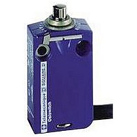
XCMD2110L1
Manufacturer Part Number
XCMD2110L1
Description
LIMIT SWITCH, 1NO.1NC, 240VAC, 250VDC, 6A
Manufacturer
SQUARE D
Datasheet
1.XCKD2102N12.pdf
(246 pages)
Specifications of XCMD2110L1
Actuator Style
Top Plunger
Operating Force Max
0.06N
Switch Operation
(ON)
Contact Voltage Ac Max
240V
Contact Voltage Dc Max
250V
Contact Current Ac Max
6A
Contact Current Dc Max
6A
Lead Free Status / RoHS Status
Contains lead / RoHS non-compliant


Limit Switches
Selection Guide
Osiswitch
22
Compliance with standards
The majority of Telemecanique
as CENELEC), or international standards (such as IEC). These standards rigidly stipulate the characteristic requirements of the designated products (for example
IEC 60947 relating to low voltage switchgear and controlgear).
These products, when correctly used, enable the production of control equipment assemblies, machine control equipment or installations conforming to their own
specific standards (for example IEC 60204 for the electrical equipment of industrial machines).
IEC 60947-5-1
Insulation coordination (and dielectric strength)
Terminal connections
Switching capacity
Positive opening operation (IEC 60947-5-1 Appendix K)
Electrical symbols for contacts
Symbol for positive opening
CENELEC EN 50047
The European standards organization CENELEC, which has 14 member countries, has defined in this standard the first type of limit switch.
This standard defines 4 variants of devices (forms A, B, C, E).
Limit switches XCKP, XCKD and XCKT conform to standard EN 50047.
Form A, with roller lever
Form C, with end roller plunger
10 (1)
2,5 (1)
50 (2)
© 1997–2007 Schneider Electric All Rights Reserved
5 (1)
10 (1)
30 (2)
®
12,5 (1)
XC Product Overview
E
P
®
brand products comply to national standards (such as French NF C standards, German DIN standards), European standards (such
31
(2)
H
H
P
P
A
•
•
•
•
•
Form B, with end plunger (rounded)
1. Minimum value
2. Maximum value
Form E, with roller lever for 1 direction of actuation
The standard IEC 60664 defines 4 categories of prospective transient overvoltages. It is important for the user
to select control circuit components which are able to withstand these overvoltages. To these ends, the
manufacturer states the rated impulse withstand voltage (U imp) applicable to the product.
The cabling capacity, mechanical robustness and durability of the terminals, as well as the ability to resist
loosening, are verified by standardized tests.
Terminal reference marking conforms to standard EN 50013.
With maximum electrical load. A single designation (A300 for example) enables indication of the contact block
characteristics related to its utilization category.
For contacts used in safety applications (end of travel, emergency stop device, etc.) the assurance of positive
opening is required (see IEC 60204, EN 60204) after each test, the opening of the contact being verified by
testing with an impulse voltage (2500 V).
12,5
10 (1)
10
5 (1)
2
12,5
•
the 2 contacts are
the same polarity.
•
Form Za,
Simplified version
H
30 (2)
P
A: reference axis
H: differential travel
P
•
the 2 contacts are electrically separate.
•
Form Zb,
Complete symbol
P: tripping point
E: cable entry
03/2007
Related parts for XCMD2110L1
Image
Part Number
Description
Manufacturer
Datasheet
Request
R


Part Number:
Description:
Pushbutton, Non-Illum'd Red "STOP", Momentary, 1NO-1NC, Square 30mm, 10A, 600V
Manufacturer:
SQUARE D
Datasheet:

Part Number:
Description:
KITS,TWIDO? PROGRAMMABLE CONTROLLERS,KITS,TWIDOPACK STARTER KIT - ADVANCED LEVEL,PROGRAMMABLE CONTROLLERS,TWIDO? PROGRAMMABLE CONTROLLERS ,SQUARE D
Manufacturer:
SQUARE D

Part Number:
Description:
LAMPS,INDICATOR,STACKABLE,LAMPS, STACKABLE INDICATOR,VISUAL INDICATING SIGNALS,XVB SERIES INDICATING BANKS ,SQUARE D
Manufacturer:
SQUARE D
Part Number:
Description:
LAMPS,INDICATOR,STACKABLE,LAMPS, STACKABLE INDICATOR,VISUAL INDICATING SIGNALS,XVB SERIES INDICATING BANKS ,SQUARE D
Manufacturer:
SQUARE D
Datasheet:
Part Number:
Description:
I/O EXTENDER MODULE 4 D IN & 2 D OUTPUT
Manufacturer:
SQUARE D
Datasheet:
Part Number:
Description:
CB ACCESSORY, UNDERVOLTAGE TRIP 48V DC
Manufacturer:
SQUARE D
Datasheet: