XCMD2110L1 SQUARE D, XCMD2110L1 Datasheet - Page 24
XCMD2110L1
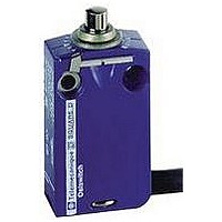
Manufacturer Part Number
XCMD2110L1
Description
LIMIT SWITCH, 1NO.1NC, 240VAC, 250VDC, 6A
Manufacturer
SQUARE D
Datasheet
1.XCKD2102N12.pdf
(246 pages)
Specifications of XCMD2110L1
Actuator Style
Top Plunger
Operating Force Max
0.06N
Switch Operation
(ON)
Contact Voltage Ac Max
240V
Contact Voltage Dc Max
250V
Contact Current Ac Max
6A
Contact Current Dc Max
6A
Lead Free Status / RoHS Status
Contains lead / RoHS non-compliant


Limit Switches
Osiswitch
XEP and XC0
24
NC
NO
Introduction
XEP3
XC0
Terminology
Mechanical characteristics
T1: bounce time
T: changeover time
Mounting
Operating speed and rate
A B C
A B C
© 1997–2007 Schneider Electric All Rights Reserved
®
Miniature Snap Switches
T
T1
XEP4E1W
XEP4E1FD
XEP5
p
p
Electromechanical detection
Osiswitch miniature snap switches, featuring electromechanical technology, assure the
following functions:
•
•
Actuation of the operator (plunger or lever) on the miniature snap switch causes the electrical
contact to change state. This information can then be processed by a PLC controlling the
installation.
Osiswitch miniature snap switches can be used both for industrial applications and the
building sector.
Features
Osiswitch miniature snap switches incorporate a C/O snap-action, single-break contact. They
are characterized by:
•
•
•
Forces
Maximum tripping force: maximum force which must be applied to the operator to move it
from the rest (unactuated) position to the trip position (tripping point).
Minimum release force: value to which the force on the operator must be reduced to allow
the snap action mechanism to return to its rest (unactuated) position.
Maximum permissible end of travel force: maximum force that can be applied to the
operator at the end of its travel without damaging the switch.
Position / Travel
1. Tripping point: position of the operator in relation to the switch mountings (mounting hole
A. Differential travel: distance between the tripping point and the position at which the snap
2. Overtravel limit: position of the operator when an extreme force has moved it to the
B. Overtravel: distance between the tripping point and the overtravel limit.
The reference point for the figures given for forces and travel is a point F, which is situated on
the plunger in the case of a basic switch or at 3 mm (0.12 in.) from the end of the plain lever
in the case of a lever operated switch.
Changeover time
This is the time taken by the moving contact when moving from one fixed contact to another
until it becomes fully stable (contact bounce included).
This time is related to the inter-contact distance, the mechanical characteristics of the snap
action mechanism, and the mass of the moving element. However, due to the snap action
mechanisms used, the time is largely independent of the speed of operation. It is normally
less than 20 ms (including bounce times of less than 5 ms).
Operating speed and maximum usable operating rate
Our miniature snap switches are suitable for a wide range of operating speeds: generally,
from 1 mm/mn to 1 m/s (0.04 in/mn to 3.28 ft/s). The maximum usable operating rate on a
light electrical load may be as high as 10 operations/second.
Mounting and operation
To conform to the leakage paths and air gaps in standards EEC 24 - EN/IEC 61058 and
EN/IEC 60947:
•
•
•
Actuation method
Direct operation: The plunger should preferably be actuated along its axis. However, the
majority of our miniature snap switches will accept skewed operation provided the angle of
actuation is not more than 45°.
The travel of the actuator must not be limited to only reaching the tripping point. The actuator
must always be operated in such a manner that the plunger reaches a point at least 0.5 times
the stated overtravel value of the switch. Also, it should not reach its end of travel nor exceed
the maximum permissible end-of-travel force.
detection of presence or absence
detection of position.
high electrical ratings for their very small size
short tripping travel
low tripping force
center line) at the instant the switch contact changes state.
action mechanism returns to its initial state on release of the operator.
effective end of its available travel.
an insulation pad must be inserted between the snap switch and the mounting surface if
the latter is metal,
manual operation of a metal actuator must only be carried out with the aid of an
intermediate actuator made of an insulating material.
The installer must ensure adequate protection against direct contact with the output
terminals.
•
•
high repeat accuracy on the
tripping points
long service life
03/2007
Related parts for XCMD2110L1
Image
Part Number
Description
Manufacturer
Datasheet
Request
R


Part Number:
Description:
Pushbutton, Non-Illum'd Red "STOP", Momentary, 1NO-1NC, Square 30mm, 10A, 600V
Manufacturer:
SQUARE D
Datasheet:

Part Number:
Description:
KITS,TWIDO? PROGRAMMABLE CONTROLLERS,KITS,TWIDOPACK STARTER KIT - ADVANCED LEVEL,PROGRAMMABLE CONTROLLERS,TWIDO? PROGRAMMABLE CONTROLLERS ,SQUARE D
Manufacturer:
SQUARE D

Part Number:
Description:
LAMPS,INDICATOR,STACKABLE,LAMPS, STACKABLE INDICATOR,VISUAL INDICATING SIGNALS,XVB SERIES INDICATING BANKS ,SQUARE D
Manufacturer:
SQUARE D
Part Number:
Description:
LAMPS,INDICATOR,STACKABLE,LAMPS, STACKABLE INDICATOR,VISUAL INDICATING SIGNALS,XVB SERIES INDICATING BANKS ,SQUARE D
Manufacturer:
SQUARE D
Datasheet:
Part Number:
Description:
I/O EXTENDER MODULE 4 D IN & 2 D OUTPUT
Manufacturer:
SQUARE D
Datasheet:
Part Number:
Description:
CB ACCESSORY, UNDERVOLTAGE TRIP 48V DC
Manufacturer:
SQUARE D
Datasheet: