XCMD2110M12 SQUARE D, XCMD2110M12 Datasheet - Page 211
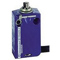
XCMD2110M12
Manufacturer Part Number
XCMD2110M12
Description
LIMIT SWITCH, 1NO.1NC, 240VAC, 250VDC, 3A
Manufacturer
SQUARE D
Datasheet
1.XCKD2102N12.pdf
(246 pages)
Specifications of XCMD2110M12
Actuator Style
Top Plunger
Operating Force Max
0.06N
Switch Operation
(ON)
Contact Voltage Ac Max
240V
Contact Voltage Dc Max
250V
Contact Current Ac Max
3A
Contact Current Dc Max
3A
Lead Free Status / RoHS Status
Contains lead / RoHS non-compliant


Limit Switches
9007C Heavy Duty Industrial
Cam Design
Position 1
Cam
Figure 1A cam design for
speeds up to 50 fpm
Figure 1B cam design for
speeds from 50 to 200 fpm
(15.2 to 60.9 mpm).
Figure 1C cam design for
speeds from 200 to 400 fpm
(60.9 to 121.9 mpm).
Figure 2
Figure 3
03/2007
trip point
60° max.
Precise
45
Cam
30° max.
(76.2 mm)
3 in. min.
(101.6 mm)
Cam
4 in. min.
45
P
Cam
P
.
Cam
15°
30°
to
60
Position 2
Cam
P
P
15°
30°
to
P
D
30
30
P
Excessive impact from improperly designed actuating systems is without question the leading cause of
premature failure of the electromechanical limit switch. At slow speed, impact is rarely troublesome, but
as speed increases, impact applied to the switch becomes a critical problem. In today's higher speed
machines, therefore, it is important to give proper consideration to correctly designed actuating systems.
These recommendations are designed to assist you in obtaining greater life from your limit switches. The
black sector in the roller indicates the recommended design limits of the angle of pressure shown in the
illustrations as “P”. Three main design and installation considerations are:
•
•
•
Considering these three factors:
•
•
•
Designing proper pressure angles
for overriding cams for electromechanical limit switches
Don't underestimate the importance of adjusting the cams and operating levers in electromechanical limit
switches to provide the proper pressure angles in every travel position. Without the means to control the
angle of pressure or the limit of override, the operating lever may spring back with damaging results.
Lever flyback usually causes double pulsing of the contacts, and places additional stresses on the
mechanical system of the limit switch. The excessive impacts absorbed from inadequately designed
actuating devices eventually leads to abnormal wear and premature failure of the limit switch.
By looking closely at the actuating angles of the cam surface, designers and engineers can obtain the
maximum operating life from electromechanical limit switches. The following recommendations help
provide a workable knowledge of proper lever and cam angles—and how they are applied to secure
optimum conditions:
•
•
•
If these guidelines are followed, the switch operating levers will always be approximately parallel with the
leading edges of the actuating surfaces or cams.
Figure 2 shows leading edge of cam about to depress and actuate the electromechanical limit switch.
The black sector of the roller indicates the recommended design limits of the angle of pressure shown in
drawings as “P”.
Figure 3 shows operating lever roller following the trailing edge of the cam on the override cycle. Unless
a one-way lever is used, the cam will operate the switch on the return cycle.
Application information
The pressure applied by the actuating mechanism to switch operating lever should approximate
direction of lever rotation with a variation not to exceed 30°.
Since the angle of pressure changes drastically with rotation of the lever, the cam must be designed
for proper pressure angles at all positions of the lever travel.
The switch operating levers should be positioned as nearly parallel with the leading edges of the
cams as possible.
The cam in Figure 1A is satisfactory for speeds up to 50 fpm (15.2 mpm)
The cam in Figure 1B is suitable for speeds up to 200 fpm (60.9 mpm) (nonuniform acceleration of
switch lever)
The cam in Figure 1C is satisfactory for speeds up to 400 fpm (121.9 mpm) (uniform or other
controlled acceleration)
Actuating cam on machinery or slide should provide a trailing edge so that upon overriding the
operating lever will not snap back.
During the approach phase, the pressure angle of the cam should not vary from the lever angle
more than 30°.
On the override phase, the angle of the trailing edge of the cam to the lever should be no more
than 60°.
© 1997–2007 Schneider Electric All Rights Reserved
211
Related parts for XCMD2110M12
Image
Part Number
Description
Manufacturer
Datasheet
Request
R


Part Number:
Description:
Pushbutton, Non-Illum'd Red "STOP", Momentary, 1NO-1NC, Square 30mm, 10A, 600V
Manufacturer:
SQUARE D
Datasheet:

Part Number:
Description:
KITS,TWIDO? PROGRAMMABLE CONTROLLERS,KITS,TWIDOPACK STARTER KIT - ADVANCED LEVEL,PROGRAMMABLE CONTROLLERS,TWIDO? PROGRAMMABLE CONTROLLERS ,SQUARE D
Manufacturer:
SQUARE D

Part Number:
Description:
LAMPS,INDICATOR,STACKABLE,LAMPS, STACKABLE INDICATOR,VISUAL INDICATING SIGNALS,XVB SERIES INDICATING BANKS ,SQUARE D
Manufacturer:
SQUARE D
Part Number:
Description:
LAMPS,INDICATOR,STACKABLE,LAMPS, STACKABLE INDICATOR,VISUAL INDICATING SIGNALS,XVB SERIES INDICATING BANKS ,SQUARE D
Manufacturer:
SQUARE D
Datasheet:
Part Number:
Description:
I/O EXTENDER MODULE 4 D IN & 2 D OUTPUT
Manufacturer:
SQUARE D
Datasheet:
Part Number:
Description:
CB ACCESSORY, UNDERVOLTAGE TRIP 48V DC
Manufacturer:
SQUARE D
Datasheet: