XCMD2110M12 SQUARE D, XCMD2110M12 Datasheet - Page 27
XCMD2110M12
Manufacturer Part Number
XCMD2110M12
Description
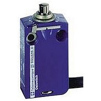
LIMIT SWITCH, 1NO.1NC, 240VAC, 250VDC, 3A
Manufacturer
SQUARE D
Datasheet
1.XCKD2102N12.pdf
(246 pages)
Specifications of XCMD2110M12
Actuator Style
Top Plunger
Operating Force Max
0.06N
Switch Operation
(ON)
Contact Voltage Ac Max
240V
Contact Voltage Dc Max
250V
Contact Current Ac Max
3A
Contact Current Dc Max
3A
Lead Free Status / RoHS Status
Contains lead / RoHS non-compliant


Limit Switches
Osiswitch
Subminiature (DIN 41635 B format, sealed) and Sub-subminiature (DIN 41635 D format)
03/2007
Switch type
Environmental characteristics
Lever fixing position (1)
Switch actuation
Product certifications
Degree of protection
Operating temperature
Materials
Mechanical characteristics
Maximum tripping force,
N (oz)
Minimum release force,
N (oz)
Maximum permissible
end of travel force, N (lb)
Tripping point (TP) (2)
Maximum differential travel
Minimum overtravel
Inter-contact distance
Mechanical durability
Electrical characteristics
Operational characteristics
Thermal current
Connection
Operating curves
XEP4E1••
1.
2.
2x10
Miniature snap switches fitted with a lever are supplied with the lever fixed in position A (see page 26).
For basic (plunger) snap switches, it is possible to fix a lever in position A or B, depending on the required tripping conditions (see page 26).
Position of the operator in relation to the switch mountings (mounting hole center line), at the instant the contact changes state.
10
10
10
0,05
6
6
5
4
0,1 0,2
®
Miniature Snap Switches
0,5
1
2
5
Enclosure
Lever
Contact
Tags
XEP4
XEP5
XEP4
XEP5
XEP4
XEP5
XEP4
XEP5
XEP4
XEP5
XEP4
XEP5
XEP4
XEP5
XEP4
XEP5
XEP4
XEP5
XEP4
XEP5
XEP4
XEP5
10 A
250 V
resistive circuit
Current
a
:
Lever
fixing
position
(1)
A
B
A
B
A
B
A
B
A
B
A
B
XEP4E1••,
XEP5P1W2
Plunger
—
On end
e, IEC 60947-5-1, EN 60947-5-1, c UR us, UL 1054, EN 61058
IP 67 XEP4E1FD••, case IP 67 and tags IP 00 XEP4E1W7••, case IP 40 and tags IP 00 XEP5P1W2••
- 40...+ 105 °C XEP4E1FD••, -40...+125 °C XEP4E1W•••• and XEP5P1•••
Polyester XEP4, diallyl-phtalate XEP5
—
AgCdO XEP4E1••, Ag XEP5
Tinned brass XEP4E1W•••, gold plated brass XEP5P1••
2.5 N (8.99 oz)
2.5 N (8.99 oz)
2 N (7.19 oz)
0.80 N (2.88 oz)
0.80 N (2.88 oz)
0.40 N (1.44 oz)
10 N (2.25 lb)
10 N (2.25 lb)
10 N (2.25 lb)
8.40
8.40
8.40 mm
0.13 mm
0.13 mm
0.06 mm
0.60 mm
0.60 mm
0.10 mm
0.4 mm
0.3 mm
2 million operating cycles
0.1 million operating cycles
AC-15: B300 (Ue: 240 V, Ie: 1.5 A)
DC-13: R300 (Ue: 250 V, Ie: 0.1 A) conforming to IEC 60947-5-1, EN 60947-5-1 Appendix A
125-250 Vac 6.0 A conforming to UL 1054
6 (1) A 250 Vac 10,000 cycles conforming to EN 61058
AC-15: D300 (Ue: 240 V, Ie: 0.3 A) conforming to IEC 60947-5-1, EN 60947-5-1 Appendix A
7.5 A on 250 V (50/60 Hz)
8.5 A on 250 V (50/60 Hz)
XEP4E1W7•: 2.8 mm (0.11 in.) cable clip tags
XEP4E1FD: Pre-cabled (horizontally in-line), 3 x 0.5 mm
Solder tags
XEP5P1••
10
10
10
+/- 0.3
+/- 0.3
2
2
2
5
5
5
4
3
0,1 0,2
mm
mm
0,5
1
1
2
2
XEP4E1••A326,
XEP5P1W2Z55B
Flat lever
A
Horizontal
Stainless steel
0.63 N (2.27 oz)
1.25 N (4.50 oz)
0.80 N (2.88 oz)
0.20 N (0.72 oz)
0.40 N (1.44 oz)
0.15 N (0.54 oz)
2.5 N (0.56 lb)
5 N (1.12 lb)
—
10.7
9.6
9.20 mm
0.52 mm
0.26 mm
0.25 mm
2.40 mm
1.20 mm
—
5
© 1997–2007 Schneider Electric All Rights Reserved
+/- 1.0
+/- 1.7
10 16 A
mm
mm
1 Resistive circuit
2 Inductive circuit
250 V
Cos
Current
a
2
, length 0.5 m (1.6 ft)
0.8
XEP4E1••A454
Roller lever
A
Stainless steel, glass reinforced polyamide roller
0.83 N (2.99 oz)
1.67 N (6.01 oz)
0.27 N (0.97 oz)
0.53 N (1.91 oz)
6.67 N (1.50 lb)
—
15.5
14.5
—
0.39 mm
0.20 mm
—
1.80 mm
0.90 mm
—
—
—
3.33 N (0.75 lb)
+/- 1.4
+/- 0.9
mm
mm
27
Related parts for XCMD2110M12
Image
Part Number
Description
Manufacturer
Datasheet
Request
R


Part Number:
Description:
Pushbutton, Non-Illum'd Red "STOP", Momentary, 1NO-1NC, Square 30mm, 10A, 600V
Manufacturer:
SQUARE D
Datasheet:

Part Number:
Description:
KITS,TWIDO? PROGRAMMABLE CONTROLLERS,KITS,TWIDOPACK STARTER KIT - ADVANCED LEVEL,PROGRAMMABLE CONTROLLERS,TWIDO? PROGRAMMABLE CONTROLLERS ,SQUARE D
Manufacturer:
SQUARE D

Part Number:
Description:
LAMPS,INDICATOR,STACKABLE,LAMPS, STACKABLE INDICATOR,VISUAL INDICATING SIGNALS,XVB SERIES INDICATING BANKS ,SQUARE D
Manufacturer:
SQUARE D
Part Number:
Description:
LAMPS,INDICATOR,STACKABLE,LAMPS, STACKABLE INDICATOR,VISUAL INDICATING SIGNALS,XVB SERIES INDICATING BANKS ,SQUARE D
Manufacturer:
SQUARE D
Datasheet:
Part Number:
Description:
I/O EXTENDER MODULE 4 D IN & 2 D OUTPUT
Manufacturer:
SQUARE D
Datasheet:
Part Number:
Description:
CB ACCESSORY, UNDERVOLTAGE TRIP 48V DC
Manufacturer:
SQUARE D
Datasheet: