XCMD2115L1 SQUARE D, XCMD2115L1 Datasheet - Page 209
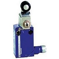
XCMD2115L1
Manufacturer Part Number
XCMD2115L1
Description
LIMIT SWITCH, 1NO.1NC, 240VAC, 250VDC, 6A
Manufacturer
SQUARE D
Datasheet
1.XCKD2102N12.pdf
(246 pages)
Specifications of XCMD2115L1
Actuator Style
Roller Lever
Operating Force Max
0.1N
Switch Operation
(ON)
Contact Voltage Ac Max
240V
Contact Voltage Dc Max
250V
Contact Current Ac Max
6A
Contact Current Dc Max
6A
Lead Free Status / RoHS Status
Contains lead / RoHS non-compliant


Limit Switches
9007C Heavy Duty Industrial
Technical Information
Recommended
overtravel
5° min. to 15°
use additional
overtravel available
for set up and
emergency only
Figure 6
L1
Figure 7—Contacts connected to
opposite polarities.
Line to line short (bold line) can
occure through arc drawn when
contacts operate
L1
03/2007
Figure 8—Contacts connected to
same polarity. Line to line short
cannot occur when contacts
operate
L1
L1
Make these angles approximately
M2
the same 45° recommended
M2
Incorrect
Correct
0.72 min.
18
Arc
Arc
0.75
19
M1
M1
M2
M2
M1
M1
L2
L2
L2
L2
Do not contact
the roller within
shaded areas
30˚
30˚
60˚
Overriding Cams
The cam trailing edge on overriding cams must also be considered for maximum switch life
(see figure 6). Lever arm snap back causes shock loads which reduce switch life. Also, with
reversing cams the trailing edge becomes a leading edge on the return stroke. The
overtravel of the limit switch should not be exceeded, but 5° minimum to 15° travel past the
trip point is recommended. Additional travel should only be used for set up and emergencies.
Cam design procedures for limit switches with other than lever arm actuators vary from
switch type to switch type and are discussed along with other limit switch application design
suggestions in additional literature “Proper Application of Limit Switches” (SM444).
Contacts
• Make sure the electrical load is within limit switch contact ratings.
• The single pole, double throw contacts of a snap switch used in a limit switch should not be
used on opposite polarities. When load M1 is connected between the contact and line L2,
and load M2 is connected between the other contact and line L1 (figure 7), a line-to-line short
(bold line) can occur through the arc, which may be drawn as the contacts operate. When
contacts are connected to the same polarity (figure 8), this line-to-line short cannot occur.
• The same result can occur if different power sources are connected to the single-pole,
double-throw contacts of a snap switch.
• With limit switches having reed contacts, some form of transient protection should be used.
This protects the small contacts from damaging surges and increases contact life.
Coolant
• When possible, avoid mounting limit switches where they will be constantly exposed to
coolant, chips, etc. Although designed for such applications, switches last longer when not
exposed to these contaminants.
• Make sure cover screws are tightened to ensure a good oiltight seal.
• When possible, avoid using fire-resistant coolants of the phosphate ester type. Equipment
exposed to these coolants requires special seals and gaskets. Viton
to these types of coolants, is the standard shaft seal material on Type C lever arm types. If
required, all gaskets, as well as boots on plunger types, can be furnished in Viton material.
Recommendations for Conduit Installation
Limit switch leakage is often traced to the conduit system. Coolant or condensation in the
conduit line can enter the switch through the conduit entry. Oil tightness depends on the
condition of the conduit connection and seal. Recommendations for installing conduit to
position switches are as follows:
• To ensure an oiltight seal, use thread sealant and a conduit seal or a sealing bushing
around the conduit fitting. Otherwise, the fitting probably will leak.
• Limit switches should be installed with the conduit end down whenever possible.
• If condensation or moisture is present inside the conduit, a Square D
inserted into the conduit entry. The conduit fitting can then be connected in the normal
manner. Thread sealant and a sealing bushing must still be used.
• Often a junction box fills with coolant and/or condensation, which backs up into the position
limit through the conduit. A simple solution is to drill a hole in the bottom of the junction box to
allow the liquid to drain out.
• If conduit leakage is severe, pre-wired and potted position limit (Forms Y184• and Y185•)
should be used. The switches are pre-wired with either individual wires or multiconductor
STOWA cord, and the receptacle is sealed with a potting material.
• The Square D limit switch is available with a pre-wired male plug receptacle. The
connector provides an effective oiltight seal when used with the appropriate female
connector cord.
© 1997–2007 Schneider Electric All Rights Reserved
®
fluoroelastomer, resistant
®
conduit seal can be
209
Related parts for XCMD2115L1
Image
Part Number
Description
Manufacturer
Datasheet
Request
R


Part Number:
Description:
Pushbutton, Non-Illum'd Red "STOP", Momentary, 1NO-1NC, Square 30mm, 10A, 600V
Manufacturer:
SQUARE D
Datasheet:

Part Number:
Description:
KITS,TWIDO? PROGRAMMABLE CONTROLLERS,KITS,TWIDOPACK STARTER KIT - ADVANCED LEVEL,PROGRAMMABLE CONTROLLERS,TWIDO? PROGRAMMABLE CONTROLLERS ,SQUARE D
Manufacturer:
SQUARE D

Part Number:
Description:
LAMPS,INDICATOR,STACKABLE,LAMPS, STACKABLE INDICATOR,VISUAL INDICATING SIGNALS,XVB SERIES INDICATING BANKS ,SQUARE D
Manufacturer:
SQUARE D
Part Number:
Description:
LAMPS,INDICATOR,STACKABLE,LAMPS, STACKABLE INDICATOR,VISUAL INDICATING SIGNALS,XVB SERIES INDICATING BANKS ,SQUARE D
Manufacturer:
SQUARE D
Datasheet:
Part Number:
Description:
I/O EXTENDER MODULE 4 D IN & 2 D OUTPUT
Manufacturer:
SQUARE D
Datasheet:
Part Number:
Description:
CB ACCESSORY, UNDERVOLTAGE TRIP 48V DC
Manufacturer:
SQUARE D
Datasheet: