XCMD2115L1 SQUARE D, XCMD2115L1 Datasheet - Page 226
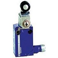
XCMD2115L1
Manufacturer Part Number
XCMD2115L1
Description
LIMIT SWITCH, 1NO.1NC, 240VAC, 250VDC, 6A
Manufacturer
SQUARE D
Datasheet
1.XCKD2102N12.pdf
(246 pages)
Specifications of XCMD2115L1
Actuator Style
Roller Lever
Operating Force Max
0.1N
Switch Operation
(ON)
Contact Voltage Ac Max
240V
Contact Voltage Dc Max
250V
Contact Current Ac Max
6A
Contact Current Dc Max
6A
Lead Free Status / RoHS Status
Contains lead / RoHS non-compliant


Limit Switches
R.B.Denison
L100, L300 Mill and Foundry Switches, L140, L2153 Cable Pulls, L529 Belt Conveyor
226
Description
L100W Switches
Use the L100W Mill switches instead of other limit switches in the
following applications:
•
•
•
f L switches are not preceded by 9007. They are known as the
R.B. Denison
slack cable pull switches in the product offering.
L300W Switches
The L300W Foundry switches are for use in foundries or mills
where the applications described above are required, and where
falling foundry sand or similar material could build up and jam the
operating mechanism. The shaft has a dust boot and extends
from the switch case, preventing sand build up around the shaft.
The devices can withstand hot falling sand up to 300° F (149° C).
Features L100, L300, L140, L2153, L525
•
•
•
•
•
•
•
•
•
•
•
•
•
•
•
– The booted shaft design prevents penetration of foreign
– Heavy duty stainless steel springs and hardened spring
– Same parameters as L100 models, except that the distance
Where the current load exceeds the typical heavy duty limit
switch contact rating of 10 A and falls within the range of up to
20 A continuous.
Where an operating sequence is required that is not possible
on other limit switches (35 choices with the L switches).
Where higher reset forces are required due to foreign material
interfering with lever arm operation, or where long heavy arms
must reset against gravity.
Captive cover screws
Heavy duty snap action mechanism prevents teasing or false
contact opening.
Positive trip action prevents the lever from slipping around the
0.5 in. (12.7 mm) shaft even if not properly tightened.
High current capability. 20 A maximum continuous
Isolated (no polarity) double and triple circuits with double
break (throw) action
Wide 0.25 in. (6.3 mm) contact gap ensures very high shock
and vibration resistance.
Easy to access contacts allow for easy inspection and
replacement.
Stamped contact configuration number for easy identification
even if the switch is painted
Many contact arrangements to solve difficult applications
Model L300 is an extra heavy duty version for very aggressive
environments.
materials such as sand, dust, or grit between the shaft and the
bushing.
operators permit longer life under extreme lever fly-back and
high impact.
between the back of the switch and the lever is increased by
0.34 in. (8.6 mm).
Two and three circuits in CW, CCW, neutral position,
spring return and maintained, snap action or slow-make
slow-break, two steps (L525) are available.
2 circuit models can be CW or CCW field converted.
Wide range of options: high shock and vibration, with gold
contact, low or very high temperature
0.5 in. (12.7 mm) NPT conduit entrance standard on 2-pole
models (5 wires max.)
0.75 in. (19 mm) NPT conduit entrance standard on 3-pole
models (7 wires max.)
© 1997–2007 Schneider Electric All Rights Reserved
®
Lox Switch™ L, and include conveyor belt and
f
®
Lox-Switch™ L Severe Duty Mill and Foundry Switches
Conforming to NEMA A600 and UL508
L100, L300 Switches (fixed sequence)
L100 Mill
Page 228
Cable Pulls (fixed sequence)
L140 Mill and Foundry
Page 232
Belt Conveyors
L525 Mill and Foundry
Page 233
Lo x-S wi tch
R. B. De nis
R. B. De nis
Lo x-S wi tch
Typ e L
Lim it Sw
NE MA A6
Ma de in U.S
Typ e L
Lim it Sw itc
NE MA A6
Ma de in U.S
R. B. De nis
Lo x-S wi tch
Typ e L
Lim it Sw itc
NE MA A6
Ma de in U.S
itc h
00 P6 00
00 P6 00
00
.A.
.A.
.A.
h
h
on
on
on
L300 Foundry
Page 230
R. B. De nis
Lo x-S wi tch
Typ e L
Lim it Sw itc
NE MA A6
Ma de in U.S
00
h
.A.
on
•
L2153 Mill and Foundry
Page 232
Conveyor belt limit switches are ideal for
policing the lateral movement of belt
conveyors. When the conveyor belt shifts, it
contacts the switch roller and a 12°
movement of the lever transfers the first set
of contacts. This set is usually wired to
initiate a warning alarm system to alert the
worker that the belt is moving off the rollers.
Further lateral movement of the belt, causing
the lever to move another 8°, trips the second
set of contacts. These contacts are normally
wired to the conveyor drive system and when
actuated stop the system, minimizing
damage to the conveyor or loss of material
on the belt.
– The booted shaft design prevents
– Heavy duty stainless steel springs and
– Same parameters as L100 models,
Model L300 is an extra heavy duty
version for very aggressive environments
penetration of foreign materials such as
sand, dust, or grit between the shaft and
the bushing.
hardened spring operators permit longer
life under extreme lever fly-back and high
impact.
except that the distance between the back
of the switch and the lever is increased by
0.34 in. (8.6 mm).
R. B. De nis
Lo x-S wi tch
Typ e L
Lim it Sw itc
NE MA A6
Ma de in U.S
00 P6 00
.A.
h
on
03/2007
Related parts for XCMD2115L1
Image
Part Number
Description
Manufacturer
Datasheet
Request
R


Part Number:
Description:
Pushbutton, Non-Illum'd Red "STOP", Momentary, 1NO-1NC, Square 30mm, 10A, 600V
Manufacturer:
SQUARE D
Datasheet:

Part Number:
Description:
KITS,TWIDO? PROGRAMMABLE CONTROLLERS,KITS,TWIDOPACK STARTER KIT - ADVANCED LEVEL,PROGRAMMABLE CONTROLLERS,TWIDO? PROGRAMMABLE CONTROLLERS ,SQUARE D
Manufacturer:
SQUARE D

Part Number:
Description:
LAMPS,INDICATOR,STACKABLE,LAMPS, STACKABLE INDICATOR,VISUAL INDICATING SIGNALS,XVB SERIES INDICATING BANKS ,SQUARE D
Manufacturer:
SQUARE D
Part Number:
Description:
LAMPS,INDICATOR,STACKABLE,LAMPS, STACKABLE INDICATOR,VISUAL INDICATING SIGNALS,XVB SERIES INDICATING BANKS ,SQUARE D
Manufacturer:
SQUARE D
Datasheet:
Part Number:
Description:
I/O EXTENDER MODULE 4 D IN & 2 D OUTPUT
Manufacturer:
SQUARE D
Datasheet:
Part Number:
Description:
CB ACCESSORY, UNDERVOLTAGE TRIP 48V DC
Manufacturer:
SQUARE D
Datasheet: