XCMD2116L1 SQUARE D, XCMD2116L1 Datasheet - Page 210
XCMD2116L1
Manufacturer Part Number
XCMD2116L1
Description
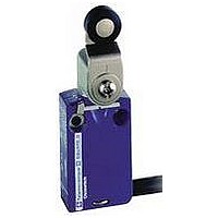
LIMIT SWITCH, 1NO.1NC, 240VAC, 250VDC, 6A
Manufacturer
SQUARE D
Datasheet
1.XCKD2102N12.pdf
(246 pages)
Specifications of XCMD2116L1
Actuator Style
Roller Lever
Operating Force Max
0.1N
Switch Operation
(ON)
Contact Voltage Ac Max
240V
Contact Voltage Dc Max
250V
Contact Current Ac Max
6A
Contact Current Dc Max
6A
Lead Free Status / RoHS Status
Contains lead / RoHS non-compliant


Limit Switches
9007C Heavy Duty Industrial
Technical Information
Terminal Identification
European (IEC) contact terminals marking
Single pole
11-12
13-14
11-12
13-14
Example of US Terminal Markings
Single pole
1-2
3-4
1-2
3-4
Wiring diagrams
Form A
SPST-NO
Form CC
DPDT
Form XX
DPST-NO-DB
210
21 - 22
13 - 14
21 - 22
13 - 14
21-22
13-14
21-22
13-14
21-22
13-14
0
© 1997–2007 Schneider Electric All Rights Reserved
C
B
D
A
P
3-4
Double pole
1
11-12
13-14
11-12
13-14
Double pole
1
1-2
3-4
1-2
st
st
pole
pole
Tripping
Resetting
Form B
SPST-NC
Form X
SPST-NO-DB
Form YY
DPST-NC-DB
Contact open
Contact closed
5-6
7-8
2
21-22
23-24
21-22
23-24
2
5-6
7-8
nd
nd
pole
pole
Each terminal is marked with 2 digits: First digit indicates the pole (circuit). The
second digit indicates the type of contact:
_1–_2 is N.C., _3–_4 is N.O.
i.e.: 11–12, 21–22 are N.C. 13–14, 23–24 are N.O.
Example of European Terminal Markings:
For switch elements without isolated contacts:
11-12 Is the N.C. contact of pole No. 1, 13-14 Is the N.O. contact of pole No. 2
For switch elements with isolated contacts:
13-14 Is the N.O. contact of pole No. 1, 21-22 Is the N.C. contact of pole No. 2
Each contact terminal is marked with one digit, i.e., 1-2, 3-4, 5-6,7-8.
Example of US Terminal Markings:
For most snap switch elements (isolated contacts not usually on US manufactured
switches):
1-2 is the N.C. contact of pole No. 1,
3-4 is the N.O. contact of pole No. 1
5-6 is the N.C. contact of pole No. 2,
7-8 is the N.O. contact of pole No. 2
Make-before-break (overlapping) SPDT: the normally open contact closes before
the normally closed contact opens.
Break-before-make (offset) SPDT: the normally closed contact opens before the
normally open contact closes.
Simultaneous make and break SPDT: the normally closed contact opens at the
same time as the normally open contact closes.
A = Maximum travel of the operator in mm or degrees.
B = Tripping travel of the contact.
C = Resetting travel of contact.
D = B-C = Differential travel.
P = Point from which positive opening is assured.
NOTE: The arrows indicate direction of actuation clockwise (CW) and return for simplicity
reasons. For counterclockwise (CCW) only direction of actuation is reversed.
Form C
SPDT
Form Y
SPST-NC-DB
Form ZZ
DPDT-DB
Form AA
DPST-NO
Form Zb
SPDT isolated contacts
Form BB
DPST-NC
Form Z
DPDT-DB
03/2007
Related parts for XCMD2116L1
Image
Part Number
Description
Manufacturer
Datasheet
Request
R


Part Number:
Description:
Pushbutton, Non-Illum'd Red "STOP", Momentary, 1NO-1NC, Square 30mm, 10A, 600V
Manufacturer:
SQUARE D
Datasheet:

Part Number:
Description:
KITS,TWIDO? PROGRAMMABLE CONTROLLERS,KITS,TWIDOPACK STARTER KIT - ADVANCED LEVEL,PROGRAMMABLE CONTROLLERS,TWIDO? PROGRAMMABLE CONTROLLERS ,SQUARE D
Manufacturer:
SQUARE D

Part Number:
Description:
LAMPS,INDICATOR,STACKABLE,LAMPS, STACKABLE INDICATOR,VISUAL INDICATING SIGNALS,XVB SERIES INDICATING BANKS ,SQUARE D
Manufacturer:
SQUARE D
Part Number:
Description:
LAMPS,INDICATOR,STACKABLE,LAMPS, STACKABLE INDICATOR,VISUAL INDICATING SIGNALS,XVB SERIES INDICATING BANKS ,SQUARE D
Manufacturer:
SQUARE D
Datasheet:
Part Number:
Description:
I/O EXTENDER MODULE 4 D IN & 2 D OUTPUT
Manufacturer:
SQUARE D
Datasheet:
Part Number:
Description:
CB ACCESSORY, UNDERVOLTAGE TRIP 48V DC
Manufacturer:
SQUARE D
Datasheet: