AZ7144 PANASONIC EW, AZ7144 Datasheet - Page 3
AZ7144
Manufacturer Part Number
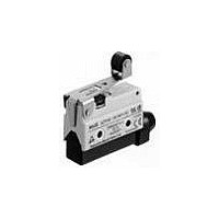
AZ7144
Description
LIMIT SWITCH, ROLLER LEVER, SPDT
Manufacturer
PANASONIC EW
Datasheet
1.AZ7121.pdf
(20 pages)
Specifications of AZ7144
Actuator Style
Roller Lever
Operating Force Max
2.75N
Contact Voltage Ac Max
250V
Contact Voltage Dc Max
115V
Contact Current Ac Max
10A
Contact Current Dc Max
400mA
Switch Terminals
Screw
Lead Free Status / RoHS Status
Lead free / RoHS Compliant


ML (AZ7)
FOREIGN STANDARDS
SPECIFICATIONS
1. Rating
2.Characteristics
* The resistance of a copper wire is not included.
3.EN60947-5-1 performance
4. Operating characteristics
Note) For the operating characteristics, refer to the TECHNICAL INFORMATION.
5. Protective characteristics
34
Rated control voltage
Actuator
Contact arrangement
Initial contact resistance, max.
Contact material
Initial insulation resistance (At 500V DC)
Initial breakdown voltage
Shock resistance
Vibration resistance
Expected life
(Min. operation)
Ambient temperature/Ambient humidity
Max. operating speed
Rated insulation voltage (Ui)
Rated impulse withstand voltage (Uimp)
Switching over voltage
Rated enclosed thermal current (Ithe)
Conditional short-circuit current
Short-circuit protection device
Protective construction
Pollution degree
Short push plunger
Push plunger
Hinge lever
Roller lever
One-way roller lever
Hinge short lever
Short roller lever
One-way short roller lever
Panel mount push plunger
Panel mount roller plunger
Panel mount cross roller plunger 5.88 {600}
Flexible rod
Protective construction
IP60
IP64
IEC
Characteristics
Standards
125V AC
250V AC
115V DC
C-UL
TÜV
Item
UL
In the free position
In the full operating position
Mechanical
Electrical
O.F. (N{gf})
5.88 {600}
5.88 {600}
1.47 {150}
1.77 {180}
1.96 {200}
2.16 {200}
2.35 {240}
2.75 {280}
5.88 {600}
5.88 {600}
1.18 {120}
max.
Standard type
–
R.F. (N{gf})
0.98 {100}
0.98 {100}
0.98 {100}
0.98 {100}
0.98 {100}
0.98 {100}
0.39 {40}
0.49 {50}
0.59 {60}
0.59 {60}
0.78 {80}
Load
min.
–
Resistive load (cos
(P.T.), max.
13.5
11.0
11.0
Pretravel
mm
2.0
2.0
8.5
6.5
6.5
2.0
2.0
2.0
25
.984
.079
.079
.335
.256
.256
.079
.079
.079
0.4A
inch
10A
10A
.531
.433
.433
(Epoxy-sealed terminal type)
File No.
Ratings
Product type : Standard type only
File No.
Ratings
Product type : Standard type only
File No.
Ratings
Product type : Standard type only
IP64 (switch)
10A fuse
Terminal mold type
250VAC
Rating
(M.D.), max.
2.5kV
2.5kV
100A
Differential
10A
Movement
1 Form C
15m * (By voltage drop 6 to 8V DC at rated current)
AgCdO contact
Min. 100 M
1,500 Vrms for 1 min Between non-consecutive terminals
2,000 Vrms for 1 min Between dead metal parts and each terminal
2,000 Vrms for 1 min Between ground and each terminal
Max. 98m/s
Max. 294m/s
55 Hz, double amplitude of 1.5 mm
10
2
–20 to +60°C
120 cpm
mm
0.8
0.8
3.2
2.4
2.4
2.0
1.5
1.5
0.8
0.8
0.8
3
]1)
Applicable product
7
(at 50 cpm)
–
.031
.031
.126
.094
.094
.079
.059
.059
.031
.031
.031
inch
10
: E122222
: 10A 250V AC
: E122222
: 10A 250V AC
: J9551204
: AC-15 2A/250V~
5
(at 20 cpm)
Inductive load (cos ]0.4)
2
{10G}
(O.T.), min.
2
Overtravel
{30G}
–4 to
mm
0.8
5.0
4.0
3.0
3.0
2.5
2.0
2.0
6.0
6.0
6.0
11
.433
.031
.197
.157
.118
.118
.098
.079
.079
.236
.236
.236
inch
0.05A
+140°F/Max. 95% R.H. (at 20°C 68°F)
6A
4A
30±0.8
44±1.2
25±2.0
40±1.9
50±2.0
25±1.3
40±1.6
50±1.6
21.8±0.8
33.3±1.2
33.3±1.2
36
Operating Position
(O.P.) mm
1.417
1.181±.031
1.732±.047
.984±.079
1.575±.75
1.969±.079
.984±.051
1.575±.063
1.969±.063
.858±.031
1.311±.047
1.311±.047
(T.T.)
inch
N.C. contact
1.5A
3A
–
DATA
1. Life curve
WIRING DIAGRAM
Order by standard part No.
Motor or lamp load
10
10
10
10
8
7
6
5
COM
Part No.
Standard type
ML
Terminal
Load current ( A )
Circuit
N.O.
N.O. contact
5
1.5A
1A
–
N.C.
10
COM
N.C.
N.O.
Related parts for AZ7144
Image
Part Number
Description
Manufacturer
Datasheet
Request
R

Part Number:
Description:
POWER RELAY, 24VDC, 30A, SPST-NO
Manufacturer:
PANASONIC EW
Datasheet:

Part Number:
Description:
POWER RELAY, SPDT, 12VDC, 10A, PC BOARD
Manufacturer:
PANASONIC EW

Part Number:
Description:
POWER RELAY, 24VDC, 5A, SPST-NO, PCB
Manufacturer:
PANASONIC EW
Datasheet:


Part Number:
Description:
SIGNAL RELAY, DPDT, 4.5VDC, 1A, SMD
Manufacturer:
PANASONIC EW
Datasheet:

Part Number:
Description:
SIGNAL RELAY, DPDT, 4.5VDC, 1A, THD
Manufacturer:
PANASONIC EW
Datasheet:

Part Number:
Description:
MINIATURE RELAY, DPDT, 24VDC, 2A, THD
Manufacturer:
PANASONIC EW


Part Number:
Description:
SIGNAL RELAY, DPDT, 5VDC, 2A, PC BOARD
Manufacturer:
PANASONIC EW
Datasheet:
Part Number:
Description:
SIGNAL RELAY, DPDT, 5VDC, 2A, SURFACE MOUNT
Manufacturer:
PANASONIC EW
Datasheet:
Part Number:
Description:
SIGNAL RELAY, DPDT, 5VDC, 2A, PC BOARD
Manufacturer:
PANASONIC EW
Datasheet:


Part Number:
Description:
PHOTOMOS RELAY, 60VDC, 400mA
Manufacturer:
PANASONIC EW
Datasheet:

Part Number:
Description:
PHOTOMOS RELAY, 400V, 150mA
Manufacturer:
PANASONIC EW
Datasheet: