3G3JX-AE022 Omron, 3G3JX-AE022 Datasheet - Page 23
3G3JX-AE022
Manufacturer Part Number
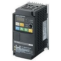
3G3JX-AE022
Description
AC Motor Drive
Manufacturer
Omron
Datasheet
1.3G3JX-A2004.pdf
(57 pages)
Specifications of 3G3JX-AE022
Supply Voltage Range
200V To 240V
No. Of Phases
Single Or Three
Power Rating
2200W
Output Voltage Max
240V
Output Frequency Max
400Hz
Mounting Type
DIN Rail
Output Voltage Min
200V
External Height
189mm
Frequency Range
0.5 To 400Hz
Rohs Compliant
Yes
External Depth
157.5mm
External Width
110mm
Lead Free Status / RoHS Status
Lead free / RoHS Compliant


● Control Circuit Terminal Specifications
● Mode Selector
For the mounting position of each selector, refer to page 30.
<Input Logic Selector>
Available to switch the input logic (source or sink) in the multi-function input terminal circuit.
<RS-485 Communication/Operator Selector>
Select the mode according to the option connected to the communications connector.
When using the 3G3AX-OP01 supplied with the Inverter, it is available regardless of the switch condition
<Frequency Reference/RUN Command Source Selector>
Switches the source for frequency reference and RUN command of the Inverter.
Input signal
Monitor
signal
Frequency
reference
input
Output signal
Relay output
signal
485/OPE
TM/PRG
MB
Relay Output
Symbol
Symbol
Symbol
SR/SK
MA
MC
Terminal
symbol
RS-485 communication/
operator selector
Frequency reference/
RUN command source
selector
PSC
AM
MA
MB
MC
SC
SC
FS
FV
FC
PC
S1
S2
S3
S4
S5
S6
P1
P2
FI
Input logic selector
Name
Name
Name
SC
External power supply terminal for input signal (input)
...At sink logic
Internal power supply output terminal for input signal (output)
...At source logic
Multi-function input S1 to S6
Select 6 functions among the 27 functions and allocate them
to from terminals S1 to S6.
Input signal common
Analog frequency monitor/Analog output current monitor
Monitor common
Frequency reference power supply
Voltage frequency reference signal
Current frequency reference signal
Frequency reference common
Multi-function Output Terminal
Select 2 functions of the Inverter status and allocate them to
terminals P1 and P2.
Output signal common
S6
Control circuit terminal block A
S5
Terminal name and function
485
OPE [Default]
TM
PRG
[Default]
S4
MB
SK [Default]
S3
Status
Status
Status
Multi-functional Compact Inverters SYSDRIVE
SR
MA
S2
MC
S1
PSC
Source logic
Sink logic
ModBus communication
Digital Operator (Option: 3G3AX-OP01)
Control terminal block (terminals): The set values in A001 and A002 are invalid.
Digital Operator setting (depends on the set values in A001 and A002.)
Frequency reference: Analog external input (FV, FI)
RUN command: Operation using the FW or RV terminal
Frequency reference: Adjuster (factory default)
RUN command: Digital Operator
FS
00 (FW) or 01 (RV) must be allocated to the multi-function input
terminals.
Available to change with the RUN command selection (A002).
FV
---
Forward/Stop
Reverse/Stop
Fault reset
External trip
Multi-step speed
reference 1
Multi-step speed
reference 2
---
Analog frequency
monitor
---
---
---
---
---
Frequency arrival
signal at a constant
speed
Signal during RUN
---
Factory default relay settings
Under normal operation: MA-MC Close
Under abnormal operation or power shutdown: MA-MC Open
Control circuit terminal block B
Default setting
Available to change with the frequency reference selection
(A001).
FI
FC
Description
Description
Description
AM
24 V DC ±10%
30 mA max.
24 V DC ±10%
100 mA max.
Contact input
Close: ON (Start)
Open: OFF (Stop)
Minimum ON time:
12 ms min.
10 V DC
10 mA max.
0-10 V DC
Input impedance 10 Ω
DC 4-20 mA
Input impedance 250 Ω
27 V DC
50 mA max.
PC
P2
MX
P1
Specifications
Series
31
Related parts for 3G3JX-AE022
Image
Part Number
Description
Manufacturer
Datasheet
Request
R

Part Number:
Description:
Drive, Adjustable Frequency, 3-Phase, 240VAC, 0.5HP, 2.6A, RS-485 Serial , IP20
Manufacturer:
Omron Automation
Datasheet:
Part Number:
Description:
Drive, Adjustable Frequency, 3-Phase, 240VAC, 5.0HP, 15.9A, RS-485 Serial , IP20
Manufacturer:
Omron Automation
Datasheet:
Part Number:
Description:
Drive, Adjustable Frequency, 3-Phase, 240VAC, 2.0HP, 7.1A, RS-485 Serial , IP20
Manufacturer:
Omron Automation
Datasheet:


Part Number:
Description:
AC Motor Drive
Manufacturer:
Omron
Datasheet:
Part Number:
Description:
G6S-2GLow Signal Relay
Manufacturer:
Omron Corporation
Datasheet:
Part Number:
Description:
Compact, Low-cost, SSR Switching 5 to 20 A
Manufacturer:
Omron Corporation
Datasheet:
Part Number:
Description:
Manufacturer:
Omron Corporation
Datasheet:
Part Number:
Description:
Manufacturer:
Omron Corporation
Datasheet:
Part Number:
Description:
Manufacturer:
Omron Corporation
Datasheet:
Part Number:
Description:
Manufacturer:
Omron Corporation
Datasheet: