3G3JX-AE022 Omron, 3G3JX-AE022 Datasheet - Page 37
3G3JX-AE022
Manufacturer Part Number
3G3JX-AE022
Description
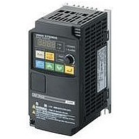
AC Motor Drive
Manufacturer
Omron
Datasheet
1.3G3JX-A2004.pdf
(57 pages)
Specifications of 3G3JX-AE022
Supply Voltage Range
200V To 240V
No. Of Phases
Single Or Three
Power Rating
2200W
Output Voltage Max
240V
Output Frequency Max
400Hz
Mounting Type
DIN Rail
Output Voltage Min
200V
External Height
189mm
Frequency Range
0.5 To 400Hz
Rohs Compliant
Yes
External Depth
157.5mm
External Width
110mm
Lead Free Status / RoHS Status
Lead free / RoHS Compliant


■ Terminal Block Specifications
● Terminal Block Position
Control circuit terminal block
Note: This illustration shows the terminal block with the Terminal block front cover removed.
● Arrangement of Main Circuit Terminals
Terminal
P/+2, N/-
+1, P/+2
symbol
EMC filter functions switching method
Main circuit terminal block
Terminal arrangement
R/L1,
U/T1,
S/L2,
V/T2,
W/T3
P/+2,
T/L3
RB
G
R/L1
Ground terminal with
short-circuit bar (shaded area)
for EMC filter multi-function
switching
G
S/L2
Main power
supply input
terminal
Inverter output
terminal
External DC
reactor
connection
terminal
Braking resistor
connection
terminals
Regenerative
braking unit
connection
terminal
Ground terminal
Terminal name
Digital Operator
EMC filter enabled
T/L3
CHARGE LED indicator
+1
P/+2
Connect the input power supply.
Connect to the 3-phase motor.
Remove the short-circuit bar between terminals
"+1" and "P/+2", and connect the optional
power factor improvement reactor (DCL).
Connect optional external braking resistors.
(The RB terminal is provided for the Inverters
with 22 kW or lower capacity.)
Connect optional regenerative braking units.
Inverter case ground terminal. Connect this
terminal to the ground.
Class D (200 V), Class D (400 V)
When not using the DCL,
keep the +1-P/+2
short-circuit bar attached.
N/-
+1-P/+2 short-
circuit bar
RO TO
U/T1
V/T2
Description
EMC filter disabled (factory default)
RB
W/T3
G
Advanced General-purpose Inverters SYSDRIVE
●Emergency Shutoff Function
• The built-in slide switch is used to enable or disable the emer-
• This function is intended to turn off the Inverter output (Stop
gency shutoff function (Factory Default: Disabled).
switching the main element) via only the multi-function input
terminal of the hardware circuit, independent of the CPU Soft-
ware.
Slide lever (factory default: OFF)
Slide switch SW1
OFF
ON
RX
Series
45
Related parts for 3G3JX-AE022
Image
Part Number
Description
Manufacturer
Datasheet
Request
R

Part Number:
Description:
Drive, Adjustable Frequency, 3-Phase, 240VAC, 0.5HP, 2.6A, RS-485 Serial , IP20
Manufacturer:
Omron Automation
Datasheet:
Part Number:
Description:
Drive, Adjustable Frequency, 3-Phase, 240VAC, 5.0HP, 15.9A, RS-485 Serial , IP20
Manufacturer:
Omron Automation
Datasheet:
Part Number:
Description:
Drive, Adjustable Frequency, 3-Phase, 240VAC, 2.0HP, 7.1A, RS-485 Serial , IP20
Manufacturer:
Omron Automation
Datasheet:


Part Number:
Description:
AC Motor Drive
Manufacturer:
Omron
Datasheet:
Part Number:
Description:
G6S-2GLow Signal Relay
Manufacturer:
Omron Corporation
Datasheet:
Part Number:
Description:
Compact, Low-cost, SSR Switching 5 to 20 A
Manufacturer:
Omron Corporation
Datasheet:
Part Number:
Description:
Manufacturer:
Omron Corporation
Datasheet:
Part Number:
Description:
Manufacturer:
Omron Corporation
Datasheet:
Part Number:
Description:
Manufacturer:
Omron Corporation
Datasheet:
Part Number:
Description:
Manufacturer:
Omron Corporation
Datasheet: