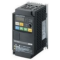
3G3JX-AE022 Omron, 3G3JX-AE022 Datasheet - Page 38

3G3JX-AE022
Manufacturer Part Number
3G3JX-AE022
Description
AC Motor Drive
Manufacturer
Omron
Datasheet
1.3G3JX-A2004.pdf
(57 pages)
Specifications of 3G3JX-AE022
Supply Voltage Range
200V To 240V
No. Of Phases
Single Or Three
Power Rating
2200W
Output Voltage Max
240V
Output Frequency Max
400Hz
Mounting Type
DIN Rail
Output Voltage Min
200V
External Height
189mm
Frequency Range
0.5 To 400Hz
Rohs Compliant
Yes
External Depth
157.5mm
External Width
110mm
Lead Free Status / RoHS Status
Lead free / RoHS Compliant
●Arrangement of Control Circuit Terminals
46
Analog
Digital
(con-
tact)
FC
FS
FV
Power supply
Frequency setting
input
Monitor output
Monitor output
Power supply
Contact
input
FV2
Advanced General-purpose Inverters SYSDRIVE
FI
AM
RUN
com-
mand
Func-
tion/
Selec-
tion
AMI
FM
P24
Terminal
symbol
FV2
AMI
P24
AM
FM
SC
FW
SN
FC
FS
FV
S1
S2
S3
S4
S5
S6
S7
S8
FI
TH
SN
Frequency reference
common
Frequency reference
power supply output
Frequency reference
input (Voltage
directive)
Auxiliary frequency
reference input
(Voltage directive)
Frequency reference
input
(Current directive)
Analog monitor
(Voltage)
Analog monitor
(Current)
Multi-function digital
output
Interface power
supply terminal
Input common
Forward rotation
command terminal
Multi-function input
Multi-function input
common
Terminal screw size M3
FW
SC
Terminal name
S8
S7
SC
S6
S5
Common terminal for the frequency setting signals (FV, FV2 and FI)
and the analog output terminals (AM and AMI). Do not connect this
terminal to the ground.
+10 V DC power supply for the FV terminal.
With a 0 V to 10 V DC voltage input, the maximum frequency is set at
10 V. To set the maximum frequency at 10 V or lower, set A014.
With a 0 to 10 V DC voltage input, the FV2 signal is added to the
frequency reference signal of the FV or FI terminal. If the setting is
changed, the frequency reference can be input even with the FV2
terminal independently.
With a 4 to 20 mA DC current input, the maximum frequency is set at
20 mA. The FI signal is only active when the AT terminal is ON.
Allocate the AT function to the multi-function input terminal.
This terminal outputs a signal selected from the "0 V to 10 V DC
Voltage Output" monitor items: Output frequency, Output current,
Output torque (with/without sign), Output voltage, Input voltage,
Electronic thermal relay load rate, LAD frequency, Motor temperature,
Cooling fin temperature, and General-purpose output.
This terminal outputs a signal selected from the "4 to 20 mA DC
Current Output" monitor items: Output frequency, Output current,
Output torque (with/without sign), Output voltage, Input voltage,
Electronic thermal relay load rate, LAD frequency, Motor temperature,
Cooling fin temperature, and General-purpose output.
This terminal outputs a signal selected from the "0 to 10 V DC Voltage
Output (PWM)" monitor items: Output frequency, Output current,
Output torque (with/without sign), Output voltage, Input voltage,
Electronic thermal relay load rate, LAD frequency, Motor temperature,
Cooling fin temperature, General-purpose output, Digital output
frequency, and Digital current monitor.
"Digital output frequency", and "Digital current monitor" output a digital
pulse at 0/10 V DC pulse voltage and 50% duty ratio.
24 V DC power supply for contact input signal.
When the source logic is selected, this terminal functions as the
contact input common terminal.
Common terminal for the interface power supply (P24) terminal,
thermistor input (TH) terminal and digital monitor (FM) terminal. When
the sink logic is selected, this terminal functions as the contact input
common terminal. Do not connect this terminal to the ground.
When the FW signal is ON, the motor runs forward. When it is OFF,
the motor decelerates and stops.
Select 8 functions from among the 69 functions and allocate them to
from terminals S1 to S8.
Note: Only terminals S1 and S3 can be used for the emergency shutoff
The sink and source logic for contact input can be switched by
connecting a short-circuit bar on the control terminal block.
Short-circuiting P24 and SC → Sink logic, Short-circuiting SC and SN
→ Source logic
To drive contact input via an external power supply, remove the short-
circuit bar and connect terminal SN to the external interface circuit.
S4
function. For details, refer to Emergency Shutoff Function on
page 45.
S3
S2
S1
P5
P4
PC
RX
Description
P3
P2
Series
P1
MC
MA
MB
---
Allowable load current:
20 mA max.
Input impedance 10 kΩ
Allowable input voltage
range: −0.3 to +12 V DC
Input impedance 10 kΩ
Allowable input voltage
0 to ±12 V DC
Input impedance 100 Ω
Allowable max. current:
24 mA
Allowable max. current:
2 mA
Allowable load
impedance: 250 Ω max.
Allowable max. current:
1.2 mA
Max. frequency: 3.6 kHz
Allowable max. output
current: 100 mA
---
[Contact input ON
condition]
Voltage between each
input terminal and the SN
terminal: 18 V DC or
more.
Input impedance between
each input terminal and
the SN terminal: 4.7 kΩ
Allowable max. voltage:
Voltage between each
input terminal and the SN
terminal: 27 V DC
Load current at 27 V DC
power supply voltage:
Approx. 5.6 mA
---
Specifications


