3G3JX-AE022 Omron, 3G3JX-AE022 Datasheet - Page 43
3G3JX-AE022
Manufacturer Part Number
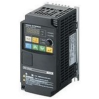
3G3JX-AE022
Description
AC Motor Drive
Manufacturer
Omron
Datasheet
1.3G3JX-A2004.pdf
(57 pages)
Specifications of 3G3JX-AE022
Supply Voltage Range
200V To 240V
No. Of Phases
Single Or Three
Power Rating
2200W
Output Voltage Max
240V
Output Frequency Max
400Hz
Mounting Type
DIN Rail
Output Voltage Min
200V
External Height
189mm
Frequency Range
0.5 To 400Hz
Rohs Compliant
Yes
External Depth
157.5mm
External Width
110mm
Lead Free Status / RoHS Status
Lead free / RoHS Compliant


Protective and Diagnostic Functions
●Error Code List
Display on Digital
Operator
ek0k1.
ek0k2.
ek0k3.
ek0k4.
ek0k5.
ek0k6.
ek0k7.
ek0k8.
ek0k9.
ek1k0.
ek1k1.
ek1k2.
ek1k3.
ek1k4.
ek1k5.
ek1k6.
ek2k0.
ek2k1.
ek2k3.
ek2k4.
ek2k5.
ek3k0.
ek3k5.
ek3k6.
ek3k7.
ek3k8.
ek4k1.
Overcurrent protection
Overload protection
Braking resistor overload
protection
Overvoltage protection
EEPROM error
Undervoltage
CT error
CPU error
External trip
USP error
Grounding protection
Incoming overvoltage
protection
Momentary power
interruption protection
Temperature error when
the rotation speed of the
cooling fan decreases
Temperature error
Gate array communications
error
Input open-phase
protection
Main circuit error
IGBT error
Thermistor error
Brake error
Emergency shutoff
Overload protection in a
low speed range
Modbus communications
error
Name
*3
*2 *3
*3
*4
*1
*3
Advanced General-purpose Inverters SYSDRIVE
Constant
speed
Deceleration
Acceleration
Others
Monitors the Inverter output current and shuts off the output, displaying an error if the built-in electronic
thermal function detects overload against the motor.
Trips depending on the electronic thermal function settings.
Shuts off the output and displays an error if the usage rate of regenerative braking circuit exceeds the b090
set value.
Extremely high DC voltage between P/+2 and N/- may result in failure. This function therefore shuts off the
output and displays an error if the DC voltage between P/+2 and N/- exceeds the specified level because of
regenerative energy from the motor or increase of the incoming voltage during operation.
Trips when the DC voltage between P/+2 and N/- reaches approximately 400 V DC for 200-V class, and 800
V DC for 400-V class.
Shuts off the output and displays an error if an error occurs because of external noise and abnormal
temperature rise in the EEPROM built into the Inverter.
Note: It may become a CPU error depending on the case.
Shuts off the output if the incoming voltage drops below that specified. This is because the control circuit fails
to work properly, if the incoming voltage to the Inverter drops.
Trips when the DC voltage between P and N reaches approximately 175 V DC for 200-V class, and 345 V DC
for 400-V class.
Shuts off the output if an error occurs in the CT (current detector) built into the Inverter. Trips if the CT output
is approximately 0.6 V or more when the power is turned on.
Shuts off the output and displays an error if the internal CPU has worked erroneously or abnormally.
Note: If an abnormal value is read from EEPROM, it may become a CPU error depending on the case.
If an error occurs in the external equipment or devices, the Inverter receives the signal, and the output is shut
off. (Available with the external trip function selected)
Appears when the power is turned on with the RUN signal input into the Inverter.
(Available with the USP function selected)
Protects the Inverter if a ground fault between the Inverter output unit and the motor is detected when turning
on the power. (This function does not work when there is residual voltage in the motor.)
Appears if the incoming voltage continues to be higher than the specification value for 100 seconds while the
Inverter is stopped.
Trips when the main circuit DC voltage reaches approximately 390 V DC for 200-V class, and 780 V DC for
400-V class.
Shuts off the output when a momentary power interruption occurs for 15 ms or more.
If the shutoff time is long, it is normally recognized as a power shutoff. Note that, when restart is selected, the
Inverter restarts from recovery as long as the RUN command remains.
Appears if a decrease of the cooling fan rotation speed has been detected when the following temperature
error occurs.
Shuts off the output if the temperature has risen in the main circuit because of the high ambient temperature.
Trips when a fault is detected in communication behavior between the built-in CPU and the gate array.
Prevents Inverter damage due to input open-phase protection function when the input open-phase selection
is enabled (b006=01), and trips.
Trips when the open-phase time is approximately 1 s or more.
Trips when the gate array cannot confirm IGBT ON/OFF because of erroneous operation or main element
breakage caused by noise interfusion.
Shuts off the Inverter output to protect the main element when a momentary overcurrent, temperature error in
the main element, or drop of the main element driving power supply occurs.
(Retry operation cannot be performed after this trip.)
Shuts off the Inverter output when detecting the thermistor resistance value inside the motor connected to
the TH terminal and resulting motor temperature rise.
When 01 is selected in b120 (brake control selection), this error appears if the brake ON/OFF cannot be
recognized within the b124 set time (brake confirmation wait time) after the Inverter outputs the brake release
signal.
Shuts off the hardware output and displays an error when the EMR terminal (S3) is turned on with SW1 on
the logic board ON.
If an overload is detected in the lowest speed range of 0.2 Hz max., an electronic thermal inside the Inverter
works to shut off the Inverter output. (2nd electronic thermal level)
(However, higher frequency could remain in the error history.)
Appears when the timeout occurs because of disconnection during Modbus-RTU communication.
(Trip by the C076 setting)
If the motor is restrained or rapidly accelerated or decelerated, a large current will flow through
the Inverter, which will result in breakage. The larger than specified current then shuts off the
output and an error appears.
The protection detects this overcurrent through AC CT (current detector).
The protection circuit operates at approximately 220% of the Inverter rated output current and
a trip occurs.
Description
RX
Series
51
Related parts for 3G3JX-AE022
Image
Part Number
Description
Manufacturer
Datasheet
Request
R

Part Number:
Description:
Drive, Adjustable Frequency, 3-Phase, 240VAC, 0.5HP, 2.6A, RS-485 Serial , IP20
Manufacturer:
Omron Automation
Datasheet:
Part Number:
Description:
Drive, Adjustable Frequency, 3-Phase, 240VAC, 5.0HP, 15.9A, RS-485 Serial , IP20
Manufacturer:
Omron Automation
Datasheet:
Part Number:
Description:
Drive, Adjustable Frequency, 3-Phase, 240VAC, 2.0HP, 7.1A, RS-485 Serial , IP20
Manufacturer:
Omron Automation
Datasheet:


Part Number:
Description:
AC Motor Drive
Manufacturer:
Omron
Datasheet:
Part Number:
Description:
G6S-2GLow Signal Relay
Manufacturer:
Omron Corporation
Datasheet:
Part Number:
Description:
Compact, Low-cost, SSR Switching 5 to 20 A
Manufacturer:
Omron Corporation
Datasheet:
Part Number:
Description:
Manufacturer:
Omron Corporation
Datasheet:
Part Number:
Description:
Manufacturer:
Omron Corporation
Datasheet:
Part Number:
Description:
Manufacturer:
Omron Corporation
Datasheet:
Part Number:
Description:
Manufacturer:
Omron Corporation
Datasheet: