3G3JX-AE022 Omron, 3G3JX-AE022 Datasheet - Page 50
3G3JX-AE022
Manufacturer Part Number
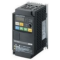
3G3JX-AE022
Description
AC Motor Drive
Manufacturer
Omron
Datasheet
1.3G3JX-A2004.pdf
(57 pages)
Specifications of 3G3JX-AE022
Supply Voltage Range
200V To 240V
No. Of Phases
Single Or Three
Power Rating
2200W
Output Voltage Max
240V
Output Frequency Max
400Hz
Mounting Type
DIN Rail
Output Voltage Min
200V
External Height
189mm
Frequency Range
0.5 To 400Hz
Rohs Compliant
Yes
External Depth
157.5mm
External Width
110mm
Lead Free Status / RoHS Status
Lead free / RoHS Compliant


Motor
Selecting the Motor Capacity
Select a motor before selecting the Inverter. Calculate the load
inertia in the application, calculate the motor capacity and torque
required to handle the load, and select an appropriate motor.
■ Simple Selection Method
With this method, you select the motor based on the output (W)
required when the motor is rotating at a steady rate. This method
does not include the involved calculations for acceleration and
deceleration, so add some extra capacity to the calculated value
when selecting the motor. This is a simple way to calculate the
size of motor needed in equipment that operates at a steady rate
for long periods, such as fans, conveyors, and mixing machines.
This method is not suitable for the following kinds of applications:
● Linear Motion: Steady Power P
●Rotational Motion: Steady Power P
■ Detailed Selection Method
With this method, you calculate the effective torque and maxi-
mum torque required in the application's operating pattern. This
method provides a detailed motor selection that matches the
operating pattern.
58
Motor
Overview of Inverter Selection
•Applications requiring sudden start-ups
•Applications where the equipment starts and stops frequently
•Applications where there is a lot of inertia in the transmission
•Applications with a very inefficient transmission system
(R.M.S. Calculation Method)
(Calculation of the Required Output)
system
η
η
T
Overview of Inverter Selection
W
N
N
T
V
η
: Load torque at load axis (N m)
: Speed of load axis (r/min)
: Efficiency of reduction mechanism (transmission)
µ
P 0 =
µ: Friction coefficient
W: Weight of moveable load (kg)
V : Speed of moveable load (m/min)
h: Efficiency of reduction mechanism (transmission)
P 0 =
T • N
9535 •
m • W • V
6120 •
η
O
η
(kW)
O
(kW)
● Calculating the Motor Shaft Conversion Inertia
Use the following equations to calculate the inertia of all of the
parts and convert that to the motor shaft conversion inertia.
● Calculating the Motor Shaft Conversion Torque and
Calculate the total combined torque required for the motor to
operate based on the acceleration torque due to the motor shaft
conversion load inertia (calculated above) and the load torque
due to friction force and the external force applied to the load.
• Acceleration Torque
• Motor Conversion Load Torque (External and Friction)
F: External
torque (N)
Effective Torque
J
J
w
w
= J
1
+ J
TW: Load torque (N m)
M
2
J
Load
Roller 2
1
+ J
3
+ J
Roller 1
J
M
D: Diameter (mm)
w
4
Gear
M
J
J
J
η
D
=
η: Gear transmission
= J
w
1
2
: Inertia of cylinder (kg m
: Inertia due to object (kg m
: Inertia (kg m
1
J
J
J
J
J
J
2
1
w
1
2
3
4
efficiency
: Inertia of cylinder 1 (kg m
: Inertia of cylinder 2 (kg m
: Inertia due to object (kg m
: Inertia due to belt (kg m
: Inertia (kg m
+ J
M
D
1
8
2
Speed (rotational)
N
2
J
D
Motor
w
=
2
1
Acceleration time (s)
t
A
+
2
M
)
1
8
M
2
D
)
2
8
2
D
2
2
J
J
J
J
J
Z
Z
Gear ratio G = Z
+
J
J
J
D
D
M: Effective mass of workpiece (kg)
J
L
w
1
2
L
1
2
2
w
1
2
: Motor shaft conversion load inertia (kg m
Time
w
: Motor gear inertia (kg m
: Load gear inertia (kg m
)
1
2
= J
: Load inertia (kg m
: Number of gear teeth on motor side
: Number of gear teeth on load side
: Inertia of roller 1 (kg m
: Inertia of roller 2 (kg m
: Inertia of entire system (kg m
+
: Diameter of roller 1 (mm)
: Diameter of roller 2 (mm)
2
= J
T
M
Friction force in general:
T
T
Z
Z
Gear (reduction) ratio G = Z
)
2
T
F = µW
)
1
L
2
2
2
L
w
1
2
4
Acceleration Torque (T
W
2
T
D: Diameter (mm)
M
M
)
)
1
: Motor shaft conversion load torque (N m)
+ G
: Number of gear teeth on motor side
: Number of gear teeth on load side
D
)
= Tw
: Load torque (N m)
D
T
J
J
η: Gear transmission efficiency
N: Motor speed (r/min)
D
A
1
2
+
= F
L
M
2
2
A
1
2
: Mass of cylinder (kg)
: Mass of object (kg)
=
: Motor shaft conversion load inertia
D
D
M
M
M
M
: Acceleration Torque
: Inertia of motor itself
2
1
2
1
2
3
4
: Diameter of cylinder 1 (mm)
: Diameter of cylinder 2 (mm)
: Mass of cylinder 1 (kg)
: Mass of cylinder 2 (kg)
: Mass of object (kg)
: Mass of belt (kg)
(J
2πN
D
D
60t
x 10
2
D
2
+
1
2
µ: Friction coefficient
W: Weight of moving parts
G
η
+ J
A
1
x 10
-6
2
M
/Z
(N m)
J
(kg m
3
w
2
2
4
J
) (kg m
D
+
M
−3
2
1
2
+
)
2
(N m)
)
J
+
M D
η
A
L
)
4
2
2
2
2
2
)
)
)
M
(N m)
(N m)
(kg m
2
1
)
)
4
4
D
1
x 10
2
1
2
/Z
2
)
)
2
-6
x 10
(kg m
(kg m
-6
(kg m
2
2
2
)
)
)
2
)
Related parts for 3G3JX-AE022
Image
Part Number
Description
Manufacturer
Datasheet
Request
R

Part Number:
Description:
Drive, Adjustable Frequency, 3-Phase, 240VAC, 0.5HP, 2.6A, RS-485 Serial , IP20
Manufacturer:
Omron Automation
Datasheet:
Part Number:
Description:
Drive, Adjustable Frequency, 3-Phase, 240VAC, 5.0HP, 15.9A, RS-485 Serial , IP20
Manufacturer:
Omron Automation
Datasheet:
Part Number:
Description:
Drive, Adjustable Frequency, 3-Phase, 240VAC, 2.0HP, 7.1A, RS-485 Serial , IP20
Manufacturer:
Omron Automation
Datasheet:


Part Number:
Description:
AC Motor Drive
Manufacturer:
Omron
Datasheet:
Part Number:
Description:
G6S-2GLow Signal Relay
Manufacturer:
Omron Corporation
Datasheet:
Part Number:
Description:
Compact, Low-cost, SSR Switching 5 to 20 A
Manufacturer:
Omron Corporation
Datasheet:
Part Number:
Description:
Manufacturer:
Omron Corporation
Datasheet:
Part Number:
Description:
Manufacturer:
Omron Corporation
Datasheet:
Part Number:
Description:
Manufacturer:
Omron Corporation
Datasheet:
Part Number:
Description:
Manufacturer:
Omron Corporation
Datasheet: