3G3JX-AE022 Omron, 3G3JX-AE022 Datasheet - Page 53
3G3JX-AE022
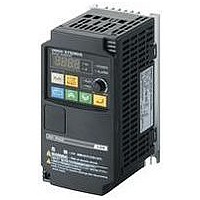
Manufacturer Part Number
3G3JX-AE022
Description
AC Motor Drive
Manufacturer
Omron
Datasheet
1.3G3JX-A2004.pdf
(57 pages)
Specifications of 3G3JX-AE022
Supply Voltage Range
200V To 240V
No. Of Phases
Single Or Three
Power Rating
2200W
Output Voltage Max
240V
Output Frequency Max
400Hz
Mounting Type
DIN Rail
Output Voltage Min
200V
External Height
189mm
Frequency Range
0.5 To 400Hz
Rohs Compliant
Yes
External Depth
157.5mm
External Width
110mm
Lead Free Status / RoHS Status
Lead free / RoHS Compliant


■ Detailed Method for Braking Resistor
If the Braking Resistor's use rate (duty factor) exceeds 10% ED
or the application requires an extremely large braking torque,
use the following method to calculate the regenerative energy
and select a Braking Resistor.
● Calculating the Required Braking Resistance
* Use the value for the braking torque calculated in Calculating the Motor Shaft
● Calculating the Average Regenerative Energy
Regenerative energy is produced when the motor is rotating in
the opposite direction of the motor torque. Use the following
equations to calculate the regenerative energy produced in each
segment of the cycle.
Note 1. The speed is positive when the motor is rotating forward and the torque
Conversion Torque and Effective Torque on page 58.
Speed
Speed
Torque
Torque
Selection
2. Use the value for the braking torque calculated in Calculating the Motor
is positive when it is in the forward direction.
Shaft Conversion Torque and Effective Torque on page 58.
Segment 1
Braking Resistor’s resistance: R ≤
Speed
Torque
V: 385 V for a 200-V Class Inverter
T: Maximum braking torque (kgf
Tm: Motor’s rated torque (N
N: Maximum speed (r/min)
Horizontal load
Vertical load
400 V for a 400-V Class Inverter
Segment 2
Segment 1
Time
Segment 2
Segment 3
Time
Time
Calculate the average regenerative energy by
adding the power produced in each segment
of the cycle and dividing by the total cycle time.
Average regenerative energy (W) =
Energy at max. speed N (r/min):
The kinetic energy is proportional
to the square of the speed, so the
regenerative energy is highest
momentarily at this point.
Max deceleration torque T (kgf
Regenerative energy is produced
when the motor's direction is
opposite the motor torque direction.
•
cm)
Pi: N x T x t x 1.048 x 10
Pi: Regenerative energy (J) produced in segmenti
N: Motor’s speed (r/min)
T: Deceleration torque (N•m)
t: Deceleration time (s)
1.048 x (T-0.2 x Tm) x N x 10
(Use the average speed if the speed varies.)
•
cm)
V
2
-1
•
cm):
(P1 + P2 + ...... + P)
1 cycle time
-1
● Selecting the Braking Resistor
Select the appropriate Braking Resistor based on the required
braking resistance and average regenerative energy that were
calculated above.
Note 1. The internal braking transistor will be damaged if a resistor is connected
• Required braking resistance ≥ Braking Resistor Unit's resis-
• Average regenerative energy ≤ Braking Resistor Unit's allow-
tance ≥ Inverter or Braking Unit's minimum resistance
able power
2. Two or more Braking Units can be connected in parallel. Use the follow-
3. Do not select the braking resistance with the results calculated above.
with a resistance below the Inverter or Braking Unit's minimum resis-
tance. If the required resistance is less than the minimum resistance, in-
crease the Inverter's capacity and replace the Inverter or Braking Unit
with one that has a minimum resistance less than the required resis-
tance.
ing equation to determine the braking resistance when driving two or
more Units.
Braking resistance (Ω) = (required braking resistance calculated above)
× (number of Units)
A rating of 150 W is not the allowed power, it is the maximum rated pow-
er in resistance units. The actual allowed power rating depends upon
the resistor.
Overview of Inverter Selection
Overview of Inverter Selection
61
Related parts for 3G3JX-AE022
Image
Part Number
Description
Manufacturer
Datasheet
Request
R

Part Number:
Description:
Drive, Adjustable Frequency, 3-Phase, 240VAC, 0.5HP, 2.6A, RS-485 Serial , IP20
Manufacturer:
Omron Automation
Datasheet:
Part Number:
Description:
Drive, Adjustable Frequency, 3-Phase, 240VAC, 5.0HP, 15.9A, RS-485 Serial , IP20
Manufacturer:
Omron Automation
Datasheet:
Part Number:
Description:
Drive, Adjustable Frequency, 3-Phase, 240VAC, 2.0HP, 7.1A, RS-485 Serial , IP20
Manufacturer:
Omron Automation
Datasheet:


Part Number:
Description:
AC Motor Drive
Manufacturer:
Omron
Datasheet:
Part Number:
Description:
G6S-2GLow Signal Relay
Manufacturer:
Omron Corporation
Datasheet:
Part Number:
Description:
Compact, Low-cost, SSR Switching 5 to 20 A
Manufacturer:
Omron Corporation
Datasheet:
Part Number:
Description:
Manufacturer:
Omron Corporation
Datasheet:
Part Number:
Description:
Manufacturer:
Omron Corporation
Datasheet:
Part Number:
Description:
Manufacturer:
Omron Corporation
Datasheet:
Part Number:
Description:
Manufacturer:
Omron Corporation
Datasheet: