3G3JX-AE022 Omron, 3G3JX-AE022 Datasheet - Page 7
3G3JX-AE022
Manufacturer Part Number
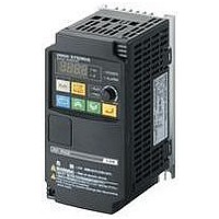
3G3JX-AE022
Description
AC Motor Drive
Manufacturer
Omron
Datasheet
1.3G3JX-A2004.pdf
(57 pages)
Specifications of 3G3JX-AE022
Supply Voltage Range
200V To 240V
No. Of Phases
Single Or Three
Power Rating
2200W
Output Voltage Max
240V
Output Frequency Max
400Hz
Mounting Type
DIN Rail
Output Voltage Min
200V
External Height
189mm
Frequency Range
0.5 To 400Hz
Rohs Compliant
Yes
External Depth
157.5mm
External Width
110mm
Lead Free Status / RoHS Status
Lead free / RoHS Compliant


■ Common Specifications
*1. The applicable motor is a 3-phase standard motor. For using any other type, be sure that the rated current does not exceed that of the Inverter.
*2. Output voltage decreases according to the level of the power supply voltage.
*3. The braking torque at the time of capacitor feedback is an average deceleration torque at the shortest deceleration (when it stops from 50 Hz), not a continuous
*4. Protection method complies with JEM 1030.
*5. To operate the motor at over 50/60 Hz, contact the motor manufacturer to find out the maximum allowable speed of revolution.
*6. For the stable control of the motor, the output frequency may exceed the maximum frequency set in A004 (A204) by 2 Hz max.
Enclosure rating
Control
Protective functions
Input signal Multi-function input
Output
signal
Other functions
General
specifica-
tions
Options
regeneration torque. Also, the average deceleration torque varies depending on the motor loss. The value is reduced in operation over 50 Hz. Note that no regen-
erative braking circuit is built into the Inverter. If you need a larger regenerative torque, use the optionally available regenerative braking unit and resistor.
The regenerative braking unit should be used only for short-time regeneration.
Control method
Output frequency range
Frequency precision
Frequency setting
resolution
Voltage/Frequency
characteristics
Overload current rating
Acceleration/
Deceleration time
Carrier frequency
modification range
DC injection braking
Multi-function output
Frequency monitor
Relay output
Ambient temperature
Ambient storage
temperature
Humidity
Vibration
Location
Applicable standard
*4
Item
*6
*5
Semi-closed (IP20)
Phase-to-phase sinusoidal modulation PWM
0.5 to 400 Hz
Digital command: ±0.01% of the max. frequency
Analog command:±0.4% of the max. frequency (25°C ±10°C)
Digital setting: 0.1 Hz
Analog setting: Max. frequency/1000
V/f characteristics (constant/reduced torque)
150% for 1 min
0.01 to 3000 s (line/curve selection), 2nd acceleration/deceleration setting available
2 to 12 kHz
Starts at a frequency lower than that in deceleration via the STOP command, at a value set lower than that during
operation, or via an external input. (Level and time settable.)
Overcurrent, overvoltage, undervoltage, electronic thermal, temperature error, ground-fault overcurrent at power-on
state, overload limit, incoming overvoltage, external trip, memory error, CPU error, USP trip, communication error,
overvoltage protection during deceleration, momentary power interruption protection, emergency shutoff
FW (forward), RV (reverse), CF1 to CF4 (multi-step speed), JG (jogging), DB (external DC injection braking), SET (2nd
function), 2CH (2-step acceleration/deceleration), FRS (free run), EXT (external trip), USP (USP function), SFT (soft
lock), AT (analog current input function selection), RS (reset), PTC (thermistor input), STA (3-wire startup), STP (3-wire
stop), F/R (3-wire forward/reverse), PID (PID selection), PIDC (PID integral reset), UP (UP of UP/DWN function), DWN
(DWN of UP/DWN function), UDC (data clear of UP/DWN function), OPE (forced OPE mode), ADD (frequency addition),
F-TM (forced terminal block), RDY (operation ready), SP-SET (special setting), EMR (emergency shutoff)
RUN (signal during operation), FA1 (frequency arrival signal 1), FA2 (frequency arrival signal 2), OL (overload warning
signal), OD (PID excess deviation signal), AL (alarm signal), DC (analog input disconnection detection signal), FBV (PID
FB status output), NDc (network error), LOG (logical operation result), ODc (communication option disconnected), LOC
(light load signal)
Analog output (0 to 10 V DC, 1 mA max.)
Frequency/Current signals are selectable via the AM output terminal.
The relay (SPDT contact) outputs signals corresponding to the multi-function output.
AVR function, V/f characteristic selection, upper/lower limit, 16-step speeds, starting frequency adjustment, jogging
operation, carrier frequency adjustment, PID control, frequency jump, analog gain/bias adjustment, S-shape
acceleration/deceleration, electronic thermal characteristics/level adjustment, retry function, simplified torque boost, trip
monitor, soft lock function, frequency conversion display, USP function, 2nd control function, motor rotation speed UP/
DOWN, overcurrent suppression function
−10°C to 50°C (Both the carrier frequency and output current need to be reduced at over 40°C.)
−20°C to 65°C (short-time temperature during transport)
20% to 90% RH
5.9 m/s
At a maximum altitude of 1,000 m; indoors (without corrosive gases or dust)
Complies with UL, cUL, CE standards. (Insulation distance)
Noise filter, AC/DC reactors, regenerative braking unit and resistor, etc.
2
(0.6G), 10 to 55 Hz (Complies with the test method specified in JIS C0040 (1999).)
Simple, Compact Inverters SYSDRIVE
Specifications
JX
Series
15
Related parts for 3G3JX-AE022
Image
Part Number
Description
Manufacturer
Datasheet
Request
R

Part Number:
Description:
Drive, Adjustable Frequency, 3-Phase, 240VAC, 0.5HP, 2.6A, RS-485 Serial , IP20
Manufacturer:
Omron Automation
Datasheet:
Part Number:
Description:
Drive, Adjustable Frequency, 3-Phase, 240VAC, 5.0HP, 15.9A, RS-485 Serial , IP20
Manufacturer:
Omron Automation
Datasheet:
Part Number:
Description:
Drive, Adjustable Frequency, 3-Phase, 240VAC, 2.0HP, 7.1A, RS-485 Serial , IP20
Manufacturer:
Omron Automation
Datasheet:


Part Number:
Description:
AC Motor Drive
Manufacturer:
Omron
Datasheet:
Part Number:
Description:
G6S-2GLow Signal Relay
Manufacturer:
Omron Corporation
Datasheet:
Part Number:
Description:
Compact, Low-cost, SSR Switching 5 to 20 A
Manufacturer:
Omron Corporation
Datasheet:
Part Number:
Description:
Manufacturer:
Omron Corporation
Datasheet:
Part Number:
Description:
Manufacturer:
Omron Corporation
Datasheet:
Part Number:
Description:
Manufacturer:
Omron Corporation
Datasheet:
Part Number:
Description:
Manufacturer:
Omron Corporation
Datasheet: