8536SAG12V02S SQUARE D, 8536SAG12V02S Datasheet - Page 46
8536SAG12V02S
Manufacturer Part Number
8536SAG12V02S
Description
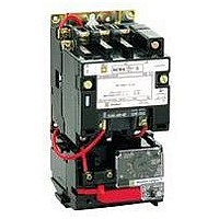
Magnetic Motor Starter
Manufacturer
SQUARE D
Datasheet
1.8502SEO2V02S.pdf
(54 pages)
Specifications of 8536SAG12V02S
No. Of Phases
Three
Power Rating
2hp
Current Rating
9A
Peak Reflow Compatible (260 C)
No
Supply Voltage Max
460VAC
Control Voltage Max
120V
Leaded Process Compatible
No
Switch Function
3PST
Supply Voltage Range
110VAC To 120VAC
Rohs Compliant
No
Contact Rating
9A
Lead Free Status / RoHS Status
Contains lead / RoHS non-compliant


Line Voltage — with Melting Alloy Overload Relays or Solid State Overload Relays – Class 8810
5/98
Special Arrangements with Three Devices
Three Type S Contactors can be mechanically
interlocked so that only one contactor can be
energized at any one time. The mechanical
interlock, pictured in Figure 2, is an interference
(non-jamming) type locking at the beginning of the
stroke of any contactor.
Factory assembled units are listed in the table
below. Figures 1 and 2 show factory assembled
and wired devices. All contactors are both
electrically and mechanically interlocked. The
class and type numbers listed only cover the
contactor and/or starter mounting arrangement,
NEMA size of the devices, and the number of
poles. A power and control wiring diagram must
accompany each order. Additional electrical
interlocks are available factory (or field) installed
in the locations shown in Figure No. 2 and Table
No. 2, Page 52. 8810 starters are supplied with
melting alloy type thermal overload relays.
For customer assembled units, the basic
mechanical interlock and base assembly can be
purchased separately. Standard Class 8502
contactors and Class 8536 starters are used in
the locations and pole arrangement shown. If
Class 8536 starters are used, it is necessary to
mount a Class 9999 Type SO bracket below the
overload block to give the block support.
For electrically interlocking customer assembled
units a Class 9999 Type SX-12, normally closed
internal interlock and/or a Class 9999 Type SX-7,
normally closed external interlock can be used.
Three Mechanically Interlocked Contactors and Starters — Factory Assembled
Ordering Information Required
1. Order complete factory assembled devices by
2. Supply wiring diagram for power and control
3. Voltage and frequency of contactor coils.
4. Select additional factory assembled electrical
5. Example of ordering information required on
Class Type
8810
8810
class and type number from table above.
connections as catalog number only covers
general contactor and starter mounting
arrangement.
interlocks from table on Page 47 specifying
interlock position letter and whether interlock
is N.O. or N.C.
factory assembled devices:
(a) Class 8810 Type SCO-45
SCO-41 3
SCO-42 4
SCO-43 . . .
SCO-44 . . .
SDO-41 . . .
SDO-42 . . .
SCO-45 3
SCO-46 4
SCO-47 . . .
SCO-48 . . .
SDO-43 . . .
SDO-44 . . .
Contactor Position — See Figure 2
No. 1 Contactor
Size and Poles
NEMA Size 1
No. of Poles
© 1998 Square D All Rights Reserved
NEMA Size 2
No. of Poles
. . .
. . .
3
4
3
4
. . .
. . .
3
4
3
4
No. 2 Contactor
Size and Poles
NEMA Size 1
No. of Poles
3
3
3
3
. . .
. . .
3
3
3
3
. . .
. . .
NEMA Size 2
No. of Poles
. . .
. . .
. . .
. . .
3
3
. . .
. . .
. . .
. . .
3
3
6. For customer assembly of three mechanically
Thermal Units
Thermal units should be ordered separately. For
selection of thermal units, refer to the Catalog
Thermal Unit Selection Index R Digest. Use the
motor nameplate FLC’s (Full Load Currents) to
select thermal units.
Figure 2
Contactor, overload and external electrical
interlock positions
A
B
(b) Wired per diagram
(c) All coils — 120 volts, 60 hertz
(d) Additional electrical interlocks:
interlocked devices, order the mechanical
interlock and overload relay mounting
brackets by class and type numbers.
Cont.
OL-1
No. 3 Contactor
Size and Poles
NEMA Size 1
No. of Poles
3
3
3
3
. . .
. . .
5
5
5
5
. . .
. . .
No.
1
(which must accompany order)
C — N.O., E — N.C., and J — N.O.
C
D
E
F
NEMA Size 2
No. of Poles
. . .
. . .
. . .
. . .
3
3
. . .
. . .
. . .
. . .
5
5
Cont.
OL-2
No.
2
G
H
Overload
Relay
Position
See Fig. 3
OL-2 & -3
OL-2 & -3
K
J
Cont.
OL-3
No.
3
Number of
Thermal
Units
Required
6
6
M
L
OL-35
45
Related parts for 8536SAG12V02S
Image
Part Number
Description
Manufacturer
Datasheet
Request
R


Part Number:
Description:
Pushbutton, Non-Illum'd Red "STOP", Momentary, 1NO-1NC, Square 30mm, 10A, 600V
Manufacturer:
SQUARE D
Datasheet:
Part Number:
Description:
CB ACCESSORY, UNDERVOLTAGE TRIP 48V DC
Manufacturer:
SQUARE D
Datasheet:
Part Number:
Description:
CB ACCESSORY, TRIP UNIT
Manufacturer:
SQUARE D
Datasheet: