PAXR0010 Red Lion Controls, PAXR0010 Datasheet
PAXR0010
Specifications of PAXR0010


Related parts for PAXR0010

PAXR0010 Summary of contents
Page 1
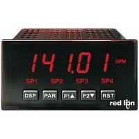
Tel +1 (717) 767-6511 Fax +1 (717) 764-0839 www.redlion.net MODEL PAX - 1/8 DIN DIGITAL INPUT PANEL METERS LISTED US LISTED R IND. CONT. EQ. 51EB GENERAL DESCRIPTION The PAX Digital Input Panel Meters offer ...
Page 2
ABLE F ONTENTS Ordering Information . . . . . . . . . . . . . . . . . . . . 2 General Meter Specifications . . . . . . . . ...
Page 3
G M ENERAL ETER 1. DISPLAY: 6 digit, 0.56" (14.2 mm) red sunlight readable or standard green LED 2. POWER: AC Versions: AC Power 250 VAC, 50/60 Hz Isolation: 2300 Vrms for 1 min. to all ...
Page 4
M PAXC - 1/8 DIN C ODEL PAXC SPECIFICATIONS MAXIMUM SIGNAL FREQUENCIES: To determine the maximum frequency for the input(s), first answer the questions with a yes ( (N). Next determine the Count Mode to be used for ...
Page 5
M PAXI - 1/8 DIN C ODEL PAXI SPECIFICATIONS MAXIMUM SIGNAL FREQUENCIES TABLE To determine the maximum frequency for the input(s), first answer the questions with a yes ( (N). Next determine the Count Mode to be used ...
Page 6
O P PTIONAL LUG WARNING: Disconnect all power to the unit before installing Plug-in cards. Adding Option Cards The PAX and MPAX series meters can be fitted with up to three optional plug- in cards. The details for each plug-in ...
Page 7
I NSTALLING THE Installation The PAX meets NEMA 4X/IP65 requirements when properly installed. The unit is intended to be mounted into an enclosed panel. Prepare the panel cutout to the dimensions shown. Remove the panel latch from the unit. ...
Page 8
I NSTALLING The Plug-in cards are separately purchased optional cards that perform specific functions. These cards plug into the main circuit board of the meter. The Plug-in cards have many unique functions when used with the PAX. The literature ...
Page 9
W IRING THE WIRING OVERVIEW Electrical connections are made via screw-clamp terminals located on the back of the meter. All conductors should conform to the meter’s voltage and current ratings. All cabling should conform to appropriate standards of good ...
Page 10
INPUT WIRING CAUTION: Sensor input common is NOT isolated from user input common. In order to preserve the safety of the meter application, the sensor input common must be suitably isolated from hazardous live earth referenced voltage; or input ...
Page 11
PAXI SERIAL COMMUNICATION WIRING RS232 Communications PAX METER (DTE) TXD RXD 12 RXD TXD 13 COMM Terminal Block Connection Figure 5 9 PIN 2 TXD 6 1 PIN 3 RXD PIN 5 COMMON FEMALE Extended Comms ...
Page 12
P ROGRAMMING THE Shaded areas represent program access that is model dependent. PROGRAMMING MODE ENTRY (PAR KEY) The meter normally operates in the Display Mode. No parameters can be programmed in this mode. The Programming Mode is entered by ...
Page 13
COUNTER A OPERATING MODE Select the operating mode for Counter A. SELECTION MODE DESCRIPTION Does not count. Count X1 Adds Input A ...
Page 14
COUNTER B OPERATING MODE Select the operating mode for Counter B. SELECTION MODE DESCRIPTION Does not count. Count X1 Adds Input B falling edge. Count X1 Adds ...
Page 15
MODULE Module 2 is the programming for rear terminal user inputs and front panel function keys. Three rear terminal user inputs are individually programmable to perform specific meter control functions. While in the Display Mode, the ...
Page 16
MAINTAINED (LEVEL) RESET AND INHIBIT The meter performs a reset and inhibits the displays configured as long as activated (maintained action). DISPLAY DESCRIPTION Counter A Counter B Counter C Maximum Minimum ...
Page 17
MODULE 3-LOC PAR x CNt rAtE Max Display Counter x Rate Display Lock-out Display Lock-out Lock-out x = Counter A , Counter B, and then Counter Setpoints Module 3 is ...
Page 18
MODULE Module 4 is the programming for the Rate parameters. For maximum input frequency, Rate assignment should be set to , the remaining related parameters are not accessible. The Rate value is shown with ...
Page 19
RATE INPUT VALUE FOR SCALING POINT 2 to Enter the corresponding Rate Input Value for the second Scaling Point by using the arrow keys. Rate Input values for scaling points can be ...
Page 20
MODULE PAXC & I Module 5 is the programming for Counter C. For maximum input frequency, the counter operating mode should be set to the remaining related parameters are not accessible. The C annunciator ...
Page 21
MODULE 6-SPt PAR SPSEL Lit-n OUt-n Setpoint Setpoint Output Select Annunciators Logic PAR Stb-n HYS-n tOFF-n Standby Setpoint Off Time Operation Hysteresis Delay Module 6 is the programming for the setpoint (alarms) output parameters. To have ...
Page 22
SETPOINT ACTION : When not using a setpoint, it should be set to For Counter Assignments: With Latch action, the setpoint output activates when the count value equals the setpoint value. The ...
Page 23
PAXC & I: SETPOINT RESET WITH DISPLAY RESET * Select , so the setpoint output will deactivate (reset) when the Setpoint Assignment ( ) counter display resets. The only exception is if the ...
Page 24
MODULE PAXI O Module 7 is the programming module for the Serial Communications Parameters. These parameters are used to match the serial settings of the PAXI with those of the host computer or other serial device, ...
Page 25
SENDING SERIAL COMMANDS AND DATA When sending commands to the meter, a string containing at least one command character must be constructed. A command string consists of a command character, a value identifier, numerical data (if writing data to the ...
Page 26
Auto/Manual Mode Register (MMR) ID: U This register sets the controlling mode for the outputs. In Auto Mode (0) the meter controls the setpoint and analog output. In Manual Mode (1) the outputs are defined by the registers SOR and ...
Page 27
COMMAND RESPONSE TIME The meter can only receive data or transmit data at any one time (half-duplex operation). During RS232 transmissions, the meter ignores commands while transmitting data, but instead uses RXD as a busy signal. When sending commands and ...
Page 28
MODULE PAXI O NLY 8-AnA PAR tYPE Analog Type Module 8 is the programming for the analog output parameters. To have an analog output signal, an analog output plug-in card needs to be installed (See Ordering ...
Page 29
PAXI: CALIBRATION The only item in the PAXI meter that can be calibrated is the Analog Output. The Count A and B values are scaled using the parameters in Module 1, Counter C value is scaled ...
Page 30
PARAMETER VALUE CHART PAX Model Number _________ Counter A & B Input Parameters - PAXC & I only DISPLAY PARAMETER COUNTER A OPERATING MODE COUNTER A RESET ACTION COUNTER A DECIMAL POSITION COUNTER A SCALE ...
Page 31
... The Company disclaims all liability for any affirmation, promise or representation with respect to the products. The customer agrees to hold Red Lion Controls harmless from, defend, and indemnify RLC against damages, claims, and expenses arising out of subsequent sales of RLC products or products containing ...
Page 32
PROGRAMMING QUICK OVERVIEW 32 ...