PAXS0010 Red Lion Controls, PAXS0010 Datasheet
PAXS0010
Specifications of PAXS0010


Related parts for PAXS0010

PAXS0010 Summary of contents
Page 1
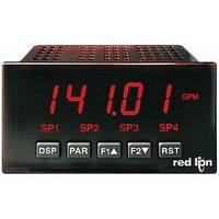
Tel +1 (717) 767-6511 Fax +1 (717) 764-0839 www.redlion.net MODEL PAX – 1/8 DIN ANALOG INPUT PANEL METERS LISTED US LISTED R IND. CONT. EQ. 51EB GENERAL DESCRIPTION ® The PAX Analog Panel Meters offer ...
Page 2
ABLE F ONTENTS Ordering Information . . . . . . . . . . . . . . . . . . 2 General Meter Specifications . . . . . . . . . . ...
Page 3
G M ENERAL ETER 1. DISPLAY: 5 digit, 0.56" (14.2 mm) red sunlight readable or standard green LEDs, (-19999 to 99999) 2. POWER: AC Versions: AC Power 250 VAC, 50/60 Hz Isolation: 2300 Vrms for 1 ...
Page 4
M PAXD - U ODEL PAXD SPECIFICATIONS INPUT RANGES: INPUT ACCURACY* ACCURACY* RANGE (18 to 28° 50°C) 0.03% of reading 0.12% of reading 200 ADC +0.03 A +0.04 A 0.03% of reading 0.12% of reading 2 mADC +0.3 ...
Page 5
M PAXH - AC T ODEL PAXH SPECIFICATIONS INPUT RANGES: Isolation To Option Card Commons and User Input Commons: 125 Vrms Isolation To AC Power Terminals: 250 Vrms MAX INPUT IMPEDANCE ACCURACY* CONTINUOUS RANGE (60 Hz) OVERLOAD 0.1% of reading ...
Page 6
M PAXT - T ODEL PAXT SPECIFICATIONS READOUT: Resolution: Variable: 0.1, 0.2, 0. degrees Scale Offset Range: -19,999 to 99,999 display units THERMOCOUPLE INPUTS: Input Impedance: 20 MΩ Lead Resistance Effect: 0.03μV/ohm ...
Page 7
O P PTIONAL LUG WARNING: Disconnect all power to the unit before installing Plug-in cards. Adding Option Cards The PAX and MPAX series meters can be fitted with up to three optional plug- in cards. The details for each plug-in ...
Page 8
I NSTALLING THE Installation The PAX meets NEMA 4X/IP65 requirements when properly installed. The unit is intended to be mounted into an enclosed panel. Prepare the panel cutout to the dimensions shown. Remove the panel latch from the unit. ...
Page 9
PAXP Jumper Selection JUMPER SELECTIONS The indicates factory setting. PAXH Jumper Selection CAUTION: To maintain the electrical safety of the meter, remove unneeded jumpers completely from the meter. Do not move the jumpers to positions other than those specified. Main ...
Page 10
PAXT Jumper Selection Main Circuit Board JUMPER JUMPER LOCATION LOCATION RTD USER INPUT INPUT 3.0 W IRING THE WIRING OVERVIEW Electrical connections are made via screw-clamp terminals located on the back of the meter. All conductors should conform to the ...
Page 11
INPUT SIGNAL WIRING PAXD INPUT SIGNAL WIRING Before connecting signal wires, the Input Range Jumper and Excitation Jumper should be verified for proper position. Voltage Signal Current Signal (self powered) (self powered) Terminal 3: +VDC Terminal 4: +ADC Terminal ...
Page 12
PAXH INPUT SIGNAL WIRING Before connecting signal wires, the Signal, Input Range and Couple Jumpers should be verified for proper position. Voltage Signal Current Signal (Amps) CAUTION: 1. Where possible, connect the neutral side of the signal (including current shunts) ...
Page 13
USER INPUT WIRING Before connecting the wires, the User Input Logic Jumper should be verified for proper position. If not using User Inputs, then skip this section. Only the appropriate User Input terminal has to be wired. Sinking Logic ...
Page 14
P ROGRAMMING THE DISPLAY MODE The meter normally operates in the Display Mode. In this mode, the meter displays can be viewed consecutively by pressing the annunciators to the left of the display indicate which display is currently shown; ...
Page 15
MODULE Refer to the appropriate Input Range for the selected meter. Use only one Input Range, then proceed to Display Decimal Point. PAXD INPUT RANGE # RANGE #"$%& SELECTION RESOLUTION " 200uA 0--2 ±200.00 µA -. ...
Page 16
DISPLAY ROUNDING* # #52 " 3 These bottom selections are not available for the PAXT. Rounding selections other than one, cause the Input Display to ‘round’ to the nearest rounding increment selected (ie. rounding of ‘5’ ...
Page 17
DISPLAY VALUE FOR SCALING POINT 2 # ?:+ / 83@@@@ to @@@@@ " 3--. - - Enter the second coordinating Display Value by using the arrow keys. This is 4&C "+,C the same for and scaling styles. (Follow the same ...
Page 18
HOLD DISPLAY # *:#83 The shown display is held but all other meter functions continue as long as activated (maintained action). " ?8F,? HOLD ALL FUNCTIONS # The meter disables processing the input, holds all display *:#83 contents, and locks ...
Page 19
SETPOINT SELECTIONS The following selections are accessible only with the Setpoint plug-in card installed. Refer to the Setpoint Card Bulletin shipped with the Setpoint plug-in card for an explanation of their operation. - ,A:6 Select main or alternate setpoints #83 ...
Page 20
MODULE MAX CAPTURE DELAY TIME* # FA86 -. - 0/J sec. " When the Input Display is above the present MAX value for the entered delay time, the meter will capture that ...
Page 21
MODULE The totalizer accumulates (integrates) the Input Display value using one of two modes. The first is using a time base. This can be used to compute a time- temperature product. The second is through a ...
Page 22
Modules 6, 7, and 8 are accessible only with the appropriate plug-in cards installed. A quick overview of each Module is listed below. Refer to the corresponding plug-in card bulletin for a more detailed explanation of each parameter selection. 5.6 ...
Page 23
MODULE DISPLAY INTENSITY LEVEL # Enter the desired Display Intensity Level (0-15) by ?8,&1 using the arrow keys. The display will actively dim or " 0 brighten as the levels are changed. This parameter also appears ...
Page 24
AC Couple Offset Calibration - PAXH It is recommended that Input Calibration be performed first. 1. With meter power removed, set the Input Range Jumper for 20 V, the Couple Jumper for DC, and set the Signal Jumper for voltage ...
Page 25
TROUBLESHOOTING PROBLEM NO DISPLAY PROGRAM LOCKED-OUT MAX, MIN, TOT LOCKED-OUT INCORRECT INPUT DISPLAY VALUE “OLOL” in DISPLAY (SIGNAL HIGH) “ULUL” in DISPLAY (SIGNAL LOW) JITTERY DISPLAY MODULES or PARAMETERS NOT ACCESSIBLE ERROR CODE (Err 1-4) DISPLAY ZERO’S AT LEVELS BELOW ...
Page 26
User Input and Function Key Parameters DISPLAY PARAMETER USr-1 USER INPUT 1 USr-2 USER INPUT 2 USr-3 USER INPUT 3 F1 FUNCTION KEY 1 F2 FUNCTION KEY 2 rSt RESET KEY Sc-F1 2nd FUNCTION KEY 1 Sc-F2 2nd FUNCTION ...
Page 27
PAX PROGRAMMING QUICK OVERVIEW 27 ...
Page 28
... The Company disclaims all liability for any affirmation, promise or representation with respect to the products. The customer agrees to hold Red Lion Controls harmless from, defend, and indemnify RLC against damages, claims, and expenses arising out of subsequent sales of RLC products or products containing components manufactured by RLC and based upon personal injuries, deaths, property ...