LRD04 TELEMECANIQUE, LRD04 Datasheet - Page 6
LRD04
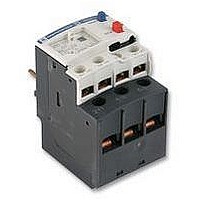
Manufacturer Part Number
LRD04
Description
RELAY, OVERLOAD, 0.4-0.6A
Manufacturer
TELEMECANIQUE
Specifications of LRD04
Overload Adjustment Current Min
0.4A
Overload Adjustment Current Max
0.63A
Approval Bodies
CSA, UL
Contact Current Max
5A
External Depth
70mm
External Length / Height
51mm
External Width
45mm
Contact Form
1 NO, 1 NC
Current, Rating
0.63 A
Current, Rating Max
0.63
Function
Overload
Mounting Type
Clamp
Primary Type
Contactor
Relay Type
Electro Mechanical
Terminal Type
Screw
Termination
Screw
Voltage, Control
575 VAC


LR2-D15pp
LR2-D25pp
LR2-D35pp
References
Characteristics:
pages 2/108 to 2/111
Schneider Electric
Dimensions:
pages 2/116 to 2/118
p Compensated relays with manual or automatic reset,
p with relay trip indicator,
p for a.c. or d.c.
p LR2-D1508 to 2553: independent mounting
Relay
setting
range
A
Class 20 (1) for connection by screw clamp terminals
2.5…4
4…6
5.5…8
7…10
9…13
12…18
17…25
23…32
17…25
23…32
30…40
37…50
48…65
55…70
63…80
p Compensated relays,
p with relay trip indicator,
p for a.c. or d.c.,
p for direct mounting on contactor or independent mounting (2).
Relay
setting
range
A
Class 10 or 10A (1) with connection using bars or connectors
60…100
90…150
Class 20 (3) with connection using bars or connectors
60…100
90…150
p Compensated relays,
p with separate outputs for alarm and tripping.
Relay
setting
range
A
Class 10 A or 20 (1) selectable with connection using bars or connectors
60…100
90…150
(1) Standard IEC 947-4-1 specifies a tripping time for 7.2 times the setting current I
class 10: between 4 and 10 seconds,
class 10 A: between 2 and 10 seconds,
class 20: between 6 and 20 seconds.
(2) Power terminals can be protected against direct finger contact by the addition of shrouds and/or insulated terminal
blocks, to be ordered separately (see page 2/90 ).
Other versions
Differential thermal overload relays for use with fuses. Class 20 tripping
Electronic differential thermal overload relays for use with fuses. Class 10 A or 20
Electronic thermal overload relays for use with balanced or unbalanced loads
- either by ordering a terminal block LA7-D1064 or LA7-D2064, see page 2/115 ,
- or by ordering the the relay pre-assembled; in this case add the suffix LA7 to the reference.
Example: LR2-D1508 becomes LR2-D1508LA7.
Fuses to be used
with the selected relay
aM
A
6
8
12
16
16
25
32
40
32
40
50
63
80
100
100
Fuses to be used
with selected relay
aM
A
100
160
125
200
Fuses to be used
with the selected relay
aM
A
100
160
TeSys protection components
3-pole thermal overload relays, model d
gG
A
10
16
20
20
25
35
50
63
50
63
100
100
125
125
160
gG
A
160
250
160
250
gG
A
160
250
Schemes:
page 2/119
Thermal overload relays for resistive circuits in category AC-1.
Please call our Customer information centre on 0870 608 8 608.
BS88
A
16
16
20
25
25
40
50
63
50
63
80
100
100
125
125
For direct mounting
For direct mounting
For use
with contactor
LC1
D09…D32
D09…D32
D09…D32
D09…D32
D12…D32
D18…D32
D25 and D32
D25 and D32
D40…D95
D40…D95
D40…D95
D50…D95
D50…D95
D65…D95
D80 and D95
beneath contactor
LC1
D115 and D150
D115 and D150
D115 and D150
D115 and D150
beneath contactor
LC1
D115 and D150
D115 and D150
Reference
LR2-D1508
LR2-D1510
LR2-D1512
LR2-D1514
LR2-D1516
LR2-D1521
LR2-D1522
LR2-D2553
LR2-D3522
LR2-D3553
LR2-D3555
LR2-D3557
LR2-D3559
LR2-D3561
LR2-D3563
Reference
LR9-D5367
LR9-D5369
LR9-D5567
LR9-D5569
Reference
LR9-D67
LR9-D69
R
Weight
Weight
Weight
2/113
0.190
0.190
0.190
0.190
0.190
0.190
0.190
0.345
0.535
0.535
0.535
0.535
0.535
0.535
0.535
0.885
0.885
0.885
0.885
0.900
0.900
kg
kg
kg
2.3
2
Related parts for LRD04
Image
Part Number
Description
Manufacturer
Datasheet
Request
R

Part Number:
Description:
Control Contactor
Manufacturer:
TELEMECANIQUE
Datasheet:

Part Number:
Description:
Control Contactor
Manufacturer:
TELEMECANIQUE
Datasheet:

Part Number:
Description:
Contactor
Manufacturer:
TELEMECANIQUE
Datasheet:

Part Number:
Description:
Contactor
Manufacturer:
TELEMECANIQUE
Datasheet:
Part Number:
Description:
Control Contactor
Manufacturer:
TELEMECANIQUE
Datasheet:

Part Number:
Description:
CONTACTOR, 2NO/2NC, 9A, 230VAC
Manufacturer:
TELEMECANIQUE
Datasheet:

Part Number:
Description:
Contactor
Manufacturer:
TELEMECANIQUE
Datasheet:

Part Number:
Description:
CONTACTOR, 4KW, 400VAC
Manufacturer:
TELEMECANIQUE
Datasheet:

Part Number:
Description:
CONTACTOR, 5.5KW, 230VAC
Manufacturer:
TELEMECANIQUE
Datasheet:
Part Number:
Description:
CONTACTOR, 5.5KW, 400VAC
Manufacturer:
TELEMECANIQUE
Datasheet:

Part Number:
Description:
PILOT LIGHT HEAD, WHITE
Manufacturer:
TELEMECANIQUE
Datasheet:

Part Number:
Description:
LENS HEAD, BA 9S
Manufacturer:
TELEMECANIQUE
Datasheet:
Part Number:
Description:
LENS HEAD, BA 9S
Manufacturer:
TELEMECANIQUE
Datasheet:

Part Number:
Description:
LED BODY, 24V
Manufacturer:
TELEMECANIQUE
Datasheet:
Part Number:
Description:
LED BODY, 48V
Manufacturer:
TELEMECANIQUE
Datasheet: