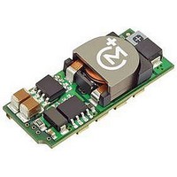
LSM2-T/6-D12NG-C Murata Power Solutions Inc, LSM2-T/6-D12NG-C Datasheet

LSM2-T/6-D12NG-C
Specifications of LSM2-T/6-D12NG-C
Related parts for LSM2-T/6-D12NG-C
LSM2-T/6-D12NG-C Summary of contents
Page 1
... Selectable-Output POL DC/DC Converters in the central supply, leaving lower cost POL regulation right at the load. Unlike linear regula- tors, the LSM2’s can deliver very high power ( Watts tiny area with no heat sinking and no external components needed. They feature quick transient response (to 25μsec) and very fast current slew rates (to 20A/μ ...
Page 2
... Not all model number combinations are available. Contact MPS. * Contact MPS (DATEL) for availability. ** The Power Good option is not available for LSM2- T/10-D12 and LSM2-T/16-D12. Models without Power Good do not install pad 8 (10/16 Amp). For 6 Amp models, pad 7 is only installed for “G” models. ...
Page 3
... Start-Up Time 2 sec (model dependent Switching Frequency LSM2-T/6 models LSM2-T/10 and -T/16 models Calculated MTBF Operating Temperature Range (Ambient) –40 to +85°C with derating Operating PC Board TemUperature Storage Temperature Range max. IN Thermal Protection/Shutdown Relative Humidity max ...
Page 4
... TECHNICAL NOTES I/O Filtering and Noise Reduction All models in the LSM2 Series are tested and specifi ed with external 1 || 10μF ceramic/tantalum output capacitors and a 22μF tantalum input capacitor. These capacitors are necessary to accommodate our test equipment and may not be required to achieve desired performance in your application ...
Page 5
... Do not exceed maximum power ratings. On/Off Control The On/Off Control pin may be used for remote on/off operation. LSM2 Series DC/DC converters are designed so that they are enabled when the control pin is left open (open collector). ...
Page 6
... If the output current exceeds it maximum rating by typically 50 the output voltage drops to less than 98 original value, the LSM2's internal overcurrent-detection circuitry immediately turns off the converter, which then goes into a "hiccup" mode. While hiccupping, the converter will continuously attempt to restart itself, go into overcurrent, and then shut down ...
Page 7
... MOSFET in a synchronous rectifi er converter sinks current at start up. The LSM2 series includes a pre-bias startup mode to prevent these initializa- tion problems. Essentially, the converter acts as a simple buck converter until the output reaches its set point voltage at which time it converts to a synchronous rectifi ...
Page 8
... W3 Models Voltage Trim Equation: The LSM2 W3 fi xed trim voltages to set the output voltage are: V (Typ.) OUT V TRIM D12 Models Voltage Trim Equation: The LSM2 D12 fi xed trim voltages to set the output voltage are: V (Typ.) OUT V TRIM 1.5V 1.8V 2.5V 3 ...
Page 9
... Selectable-Output POL DC/DC Converters Typical Performance Curves www.murata-ps.com LSM2 Series Single Output, Non-Isolated email: sales@murata-ps.com 25 Jun 2010 MDC_LSM2 Series.B09Δ Page ...
Page 10
... Tape & Reel Surface Mount Package MPS’s LSM2 series DC/DC converters are the only higher-current (16A) SMT DC/DC's that can be automatically “pick-and-placed” using standard vacuum- pickup equipment (nozzle size and style, vacuum pressure and placement speed may need to be optimized for automated pick and place) and subse- quently refl ...
Page 11
... LSM2 TAPE AND REEL SPECIFICATIONS DATEL's new-generation LSM2 SMT DC/DC converters are shipped in quantities of 150 modules per tape and reel. 2.063 1.370 2.205 (56) (52.4) (34.8) DIMENSIONS IN INCHES (mm) 0.590 (14.97) 1.102 0.158 (28) ( 0.605 (15.36) Figure 7. Tape Dimensions www.murata-ps.com LSM2 Series Single Output, Non-Isolated ...
Page 12
... Lastly, changing the timing may require reprogramming the logic sequencer or rewriting software. Sequence/Track Input A different power sequencing solution is employed on MPS’s LSM2 DC/DC con- verter. After external input power is applied and the converter stabilizes, a high impedance Sequence/Track input pin accepts an external analog voltage. The output power voltage will then track this Sequence/Track input at a one-to-one ratio up to the nominal set point voltage for that converter ...
Page 13
... Figure 13 is the same strategy as Figure 12 but with an “exclusive” timing relationship staggered approximately the same at power-up and power-down. Figure 12. Staggered or Sequential Phasing—Inclusive (Fixed Delays) Figure 13. Staggered or Sequential Phasing—Exclusive www.murata-ps.com LSM2 Series Single Output, Non-Isolated Time) OUT (Fixed Cascaded Delays) email: sales@murata-ps ...
Page 14
... R3) on POL B. We have also added an optional very small noise fi lter cap at C2. Figure 16’s circuit corresponds roughly to Figure 11’s timing for power up. (the setpoint of POL B), POL OUT www.murata-ps.com LSM2 Series Single Output, Non-Isolated Selectable-Output POL DC/DC Converters power is applied to the IN Figure 15. Self-Ramping Power Up Figure 16 ...
Page 15
... FET is at saturation, approximately +0.2V output. Keep this LOW (FALSE) pulldown current to less than 10mA. Please note that Power Good is briefl y false during Sequence ramp-up. Ignore Power Good while in transition. www.murata-ps.com LSM2 Series Single Output, Non-Isolated email: sales@murata-ps.com 25 Jun 2010 MDC_LSM2 Series.B09Δ ...
Page 16
... Drawing not to scale www.murata-ps.com LSM2 Series Single Output, Non-Isolated Selectable-Output POL DC/DC Converters I/O CONNECTIONS Pin Function P66 1 On/Off Control 2 +Input 3 Seq./Track 4 Common 5 +Output 6 Trim 7 Sense 8 ...
Page 17
... The descriptions contained herein do not imply the granting of licenses to make, use, or sell equipment constructed in accordance therewith. Specifi cations are subject to change without notice. www.murata-ps.com/locations LSM2 Series Single Output, Non-Isolated Selectable-Output POL DC/DC Converters I/O CONNECTIONS ...


