PR11-2-10.0A-XX-V AIRPAX, PR11-2-10.0A-XX-V Datasheet - Page 14
PR11-2-10.0A-XX-V
Manufacturer Part Number
PR11-2-10.0A-XX-V
Description
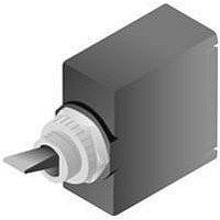
CIRCUIT BREAKER, HYD-MAG, 1P, 250V, 10A
Manufacturer
AIRPAX
Series
PRr
Datasheet
1.PP11-2-10.0A-XX-V.pdf
(16 pages)
Specifications of PR11-2-10.0A-XX-V
Input Voltage Vac
250V
No. Of Poles
1
Current Rating
10A
Interrupting Capacity
500A
Dielectric Strength
1.5kV
Trip Time
15s
Voltage Rating Vdc
32V
Leaded Process Compatible
Yes
Rohs Compliant
Yes
Lead Free Status / RoHS Status
Lead free / RoHS Compliant


73
Notes:
A A neon bulb is provided when specified for 120Vac and 250Vac operation. For operation
B An LED with 750 ft. L @ 20mA is provided in the center of the handle. Maximum power
HOw TO ORDER
The ordering code for the
SNAPAK
may be determined by following
the steps in the decision tables
shown here.
The coding given permits a self-
assigning part number, with
certain limitations (due to the
adaptability of magnetic
protectors to complex circuits),
requires a factory-assigned part
number.
The example shown is the code
for a paddle handle, single pole
(UL construction), series
circuit protector designed for
operation of a 50/60Hz/DC
circuit. A slow time delay and
rating of 5 amperes has been
indicated. Handle color is black,
and a bright nickel knurled nut,
vertical mount (ON-OFF)
indicator plate and locking ring
are to be supplied.
To determine the ordering code
for your particular SNAPAK
unit, simply follow the steps
shown, then fill in the letters
and/or numbers in the boxes.
Space is available on the circuit
breaker label for your part
number (up to 12 digits). you
may then use your own part
number to place an order or as
a reference for further
questions you may have. This
option does require a factory
assigned part number for
traceability to your drawing or
internal part number.
dissipation @ 25°C is 135mW. Continuous forward current is 20mA. Forward voltage,
typical, is 1.6v at 20mA. Reverse current, typical, is 100mA @ 3.0 volts. An external
resistor may be required to limit current to these values.
at 120Vac a 33,000 ohm, 1/2 watt external resistor is required. At 250Vac a 100,000
ohm, 1 watt external resistor is required.
SNAPAK® Series - Decision Tables
®
circuit protectors
®
*For addition of Inertia Delay an "F" may be added
+
T
PP
PR
R
CR
CPP
CPR
††††
-0
-2
-3
-41
-42
-49
-1
-4
-51
-52
-59
-61
-62
-69
CR, CPP, CPR only available in these delays
-S
to delay numbers 41, 42, 51, 52, 61 and 62 only.
†††
2
1 2
1
1
††
†
Instant 400 Hz
Instant DC-50/60 Hz
Fast DC-50/60 Hz
Slow DC-50/60 Hz
Fast w/ Inertia Wheel
DC-50/60 Hz
Slow w/ Inertia Wheel
Fast 400 Hz*
Slow 400 Hz*
Handle
Second Decision
Frequency & Delay
DC-50/60 Hz
Fast DC
Slow DC
Instant DC
Fast 50/60 Hz*
Slow 50/60 Hz*
Instant 50/60 Hz
Switch Pole or Special Delay
Paddle Handle
Push-Pull
Push-To-Reset
Rocker
Rocker
Push-Pull
Push to Reset
UL & CSA Construction
Non UL & CSA Construction
Auxilary Switch is located in the left hand pole (viewed from terminal end)
Does not meet spacings for many IEC / VDE equipment specs.
Consult factory for additional information.
* Multi-pole units with mixed construction, poles numbered left to right when viewed
from terminal end. Shunt or relay construction available in pole 2 only, other pole must be a series
or switch only construction.
**UL 489A listed, available in 1 pole series or series w/silver aux. switch. DC delay only
First Decision
+
+
+
**
**
**
1
4
2
5
Single Pole †
Single Pole ††
Two Pole †
Two Pole ††
Poles
C When ordering Paddle Handles, you may choose one item from each hardware group to add to 5th
D All units except Rocker units will have (1) hex nut installed as standard hardware for the back of a
E Switch only — no current overload protection provided.
F. CCC Approval - if CCC is required on this product, please inform Sensata to have this product
decision if such items are desired. For example, “-11ALCA” would indicate a bright nickel knurled nut,
plus a vertical mount indicator, plus a locking ring, plus #8-32 screw terminal, straight with tabs.
panel. The choices in the fifth decision table are intended for the front or visible side of the panel and
are offered for Paddle Handle configuration only. Push-Pull and Push-to-Reset configurations include
one (1) panel nut and one (1) hex nut as standard hardware.
manufacturered in our China facility
T11 - 2- 5.00A - 01-11AL- V
1
0
1
3
4
5
6
9
2
Switch Only (Note E)
Series Circuit Protector
Shunt Circuit Protector
Relay Circuit Protector ††††
Series w/ Silver Aux. Switch †††
Series w/ Gold Aux. Switch †††
Mixed Construction ( Two Pole Only )
Configurations*
3
Use three numbers to print required
current value between .100 amps
minimum and 30.0 amps maximum.
For example, use:
.100 or 2.00 or 10.0
Circuit Breaker Construction
-SW
3
Switch Only Construction
4
Rated Current
Maintained SPST & DPST
Third Decision
5
S
Quick Connects (leave blank)
Screw Terminals,
Single pole (-1) and series only
(5th decision, group V - screw
terminal option is required
when 1st decision "S" is
specified)
Terminals
Related parts for PR11-2-10.0A-XX-V
Image
Part Number
Description
Manufacturer
Datasheet
Request
R

Part Number:
Description:
Circuit Breaker Magnetic Circuit Protectors 1Pole 1A 2-Pin
Manufacturer:
AIRPAX
Datasheet:

Part Number:
Description:
CIRCUIT BREAKER, HYD-MAG, 1P, 250V, 2A
Manufacturer:
AIRPAX
Datasheet:
Part Number:
Description:
CIRCUIT BREAKER, HYD-MAG, 1P, 125V, 20A
Manufacturer:
AIRPAX
Datasheet:
Part Number:
Description:
CIRCUIT BREAKER, HYD-MAG, 1P, 250V, 1A
Manufacturer:
AIRPAX
Datasheet:
Part Number:
Description:
CIRCUIT BREAKER, HYD-MAG, 1P, 250V, 5A
Manufacturer:
AIRPAX
Datasheet: