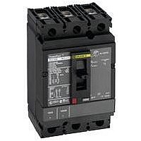
HDL36100 SQUARE D, HDL36100 Datasheet - Page 35
HDL36100
Manufacturer Part Number
HDL36100
Description
CIRCUIT BREAKER, THERMAL MAG, 3P, 100A
Manufacturer
SQUARE D
Series
PowerPactr
Type
Standardr
Specifications of HDL36100
Actuator Style
Toggle
No. Of Poles
3
Current Rating
100A
Voltage Rating Vdc
250V
Voltage Rating Vac
600V
Mounting Type
DIN Rail
Terminals
Lug
Actuator Type
Handle
Brand/series
HD Series
Characteristic
Adjustable Trip
Dimensions
6.40 (H) × 4.12 (W) × 4.36 (D) in.
Frame Type
H
Number Of Poles
3
Terminal Type
Line: Lug - Load: Lug
Voltage Rating
600/250 VAC/DC
Weight
5.00 lbs.
Wire Size
#14-3/0 AWG (Al/Cu)
Ampere Interrupting Ratings
25 k @ 240 VAC, 18k @ 480 VAC
Standards
UL489, CSA, NOM, IEC 60947, CE
Lead Free Status / RoHS Status
Lead free / RoHS Compliant


Table 45:
1
Alarm/Overcurrent Trip Switch
Switch
Alarm Switch (SD)
Alarm Switch (SD) Low-level
SDE Standard
SDE Low-level
SD and SDE Standard
SD and SDE Low-level
OF/SD Switch
© 2004–2010 Schneider Electric
All Rights Reserved
Includes SDE Adapter S29451.
SDE
1
1
Switch Catalog Numbers
1
1
Factory-
Installed Suffix
Auxiliary and Alarm Switches
Auxiliary switches provide remote information of the circuit breaker status and can thus be used for
indications, electrical locking, relays, etc.
Table 44:
Applications
Installation &
Connection
Standards
Characteristic
Supplied as Standard (Form C)
Maximum Number of Contacts
Breaking Capacity
at a Power Factor (p.f.) of 0.3
BC
BH
BD
BE
BK
BJ
Electrical Characteristics
Open/Closed (OF) Auxiliary Switch
•
Trip Indication (SD) Switch
•
•
Overcurrent Trip Switch (SDE)
•
•
The above auxiliary switches are also available in low-level versions capable of switching very low loads (e.g.,
for controlling PLCs or electronic circuits).
•
•
•
•
•
•
•
•
Field-Installable
Kit No.
S29450
S29452
S29450
S29452
S29450 (2) + S29451
S29452 (2) + S29451
Indicates the position of the circuit breaker contacts
Bell alarm indicates that the circuit breaker has tripped due to an overload, short circuit or ground fault, the
operation of a shunt trip or undervoltage trip or the “push-to-trip” button
Resets when the circuit breaker is reset
Indicates that the circuit breaker has tripped due to an overload, short circuit or ground fault
Resets when the circuit breaker is reset
The OF, SD and SDE switches snap into cavities behind the front accessory cover of the circuit breaker
One model serves for all indication functions depending on where it is fitted in the circuit breaker
The SDE function of a circuit breaker equipped with a thermal-magnetic trip unit requires the SDE adapter
The internal accessories comply with requirements of Underwriters Laboratories
UL 489 and Canadian Standard Association C22.2 No. 5-02 Standards
All internal accessories are Listed for fixed installation per UL file E103955 and Certified under CSA file LR 69561
Auxiliary switches comply with UL 489, CSA C22.2 No. 5-02 and IEC 60947-5 Standards
“Low-level” switches are not UL Recognized
+
+
Voltage
Standard (100 mA/24 V minimum load)
Vac
Vdc
Low-level (1 mA/4 V minimum load with a maximum current and voltage of 100 mA 10 V.
NOTE: NOTE: If the maximum voltage and current is exceeded, the low-level function of the switch will
be lost but the switch will continue to function as a standard switch with the following specifications.
Vac
Vdc
S29451
S29451
PowerPact
Auxiliary Switch
Contacts
1A/1B Standard
2A/2B Standard
1A/1B Gold
2A/2B Gold
240/380
480
600/690
24/48
240
380
24/48
240
380
24/48
125
250
®
H- and J-Frame Circuit Breakers
Factory-Installed
Suffix
AA
AB
AE
AF
Standard
(Silver Contacts)
4
4
6 A
6 A
6 A
2.5 A
0.5 A
0.3 A
5 A
5 A
5 A
5/2.5 A
0.5 A
0.3 A
Section 3—Accessories
Field-Installable
Kit No.
S29450
S29450 (2)
S29482
S29482 (2)
®
Inc. (UL
Low-Level
(Gold Contacts)
4
4
5 A
5 A
—
2.5 A
0.8 A
0.3 A
—
—
—
—
—
—
®
)
06/2010
35
Related parts for HDL36100
Image
Part Number
Description
Manufacturer
Datasheet
Request
R


Part Number:
Description:
Pushbutton, Non-Illum'd Red "STOP", Momentary, 1NO-1NC, Square 30mm, 10A, 600V
Manufacturer:
SQUARE D
Datasheet:

Part Number:
Description:
KITS,TWIDO? PROGRAMMABLE CONTROLLERS,KITS,TWIDOPACK STARTER KIT - ADVANCED LEVEL,PROGRAMMABLE CONTROLLERS,TWIDO? PROGRAMMABLE CONTROLLERS ,SQUARE D
Manufacturer:
SQUARE D

Part Number:
Description:
LAMPS,INDICATOR,STACKABLE,LAMPS, STACKABLE INDICATOR,VISUAL INDICATING SIGNALS,XVB SERIES INDICATING BANKS ,SQUARE D
Manufacturer:
SQUARE D
Part Number:
Description:
LAMPS,INDICATOR,STACKABLE,LAMPS, STACKABLE INDICATOR,VISUAL INDICATING SIGNALS,XVB SERIES INDICATING BANKS ,SQUARE D
Manufacturer:
SQUARE D
Datasheet:
Part Number:
Description:
I/O EXTENDER MODULE 4 D IN & 2 D OUTPUT
Manufacturer:
SQUARE D
Datasheet:
Part Number:
Description:
CB ACCESSORY, UNDERVOLTAGE TRIP 48V DC
Manufacturer:
SQUARE D
Datasheet: