HDL36100 SQUARE D, HDL36100 Datasheet - Page 4
HDL36100
Manufacturer Part Number
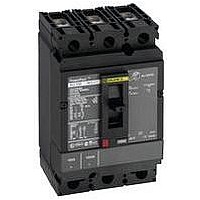
HDL36100
Description
CIRCUIT BREAKER, THERMAL MAG, 3P, 100A
Manufacturer
SQUARE D
Series
PowerPactr
Type
Standardr
Specifications of HDL36100
Actuator Style
Toggle
No. Of Poles
3
Current Rating
100A
Voltage Rating Vdc
250V
Voltage Rating Vac
600V
Mounting Type
DIN Rail
Terminals
Lug
Actuator Type
Handle
Brand/series
HD Series
Characteristic
Adjustable Trip
Dimensions
6.40 (H) × 4.12 (W) × 4.36 (D) in.
Frame Type
H
Number Of Poles
3
Terminal Type
Line: Lug - Load: Lug
Voltage Rating
600/250 VAC/DC
Weight
5.00 lbs.
Wire Size
#14-3/0 AWG (Al/Cu)
Ampere Interrupting Ratings
25 k @ 240 VAC, 18k @ 480 VAC
Standards
UL489, CSA, NOM, IEC 60947, CE
Lead Free Status / RoHS Status
Lead free / RoHS Compliant


4
PowerPact
Table of Contents
06/2010
®
H- and J-Frame Circuit Breakers
SECTION 3: ACCESSORIES
SECTION 4: WIRING DIAGRAMS
SECTION 5: DIMENSIONS
SECTION 6: TRIP CURVES
SECTION 7: MCP INSTANTANEOUS TRIP POINTS
I-Line
Plug-In and Drawout Circuit Breakers ........................................................................................... 32
Internal Accessories ...................................................................................................................... 34
Accessory Connections ................................................................................................................. 34
Auxiliary and Alarm Switches ........................................................................................................ 35
Shunt Trip (MX) and Undervoltage Trip (MN) Switches ................................................................ 36
Add-On Ground-Fault Module (GFM) ............................................................................................ 37
Earth Leakage Module (ELM) for PowerPact H- and J-Frame MCCBs ........................................ 38
Motor Operator .............................................................................................................................. 39
Rotary Operating Handles ............................................................................................................. 40
Class 9422 Cable Operating Handle ............................................................................................. 41
Circuit Breaker Enclosures and Enclosure Accessories ................................................................ 42
Locking Systems ........................................................................................................................... 43
Interlocking Systems ..................................................................................................................... 44
Installation Accessories ................................................................................................................. 44
H-Frame Dimensional Drawings .................................................................................................... 47
J-Frame Dimensional Drawings .................................................................................................... 51
Plug-In H- and J-Frame Dimensional Drawings ............................................................................ 53
Drawout H- and J-Frame Dimensional Drawings .......................................................................... 54
Mounting Dimensional Drawings ................................................................................................... 55
H- and J-Frame Door Cutout Dimensional Drawings .................................................................... 56
Plug-In Circuit Breaker Mounting ............................................................................................. 32
Parts of a Plug-In Configuration ............................................................................................... 32
Drawout Circuit Breaker Mounting ........................................................................................... 33
Chassis Functions .................................................................................................................... 33
Factory-Installed ELMs ............................................................................................................ 38
Directly-Mounted Rotary Operating Handles ........................................................................... 40
Class 9421 NEMA Door Mounted Rotary Operating Handles ................................................. 41
Variable Depth Mechanisms .................................................................................................... 42
Interlocking of Circuit Breakers With Toggle Control ............................................................... 44
Interlocking Two Circuit Breakers with Rotary Handles ........................................................... 44
Standard Motor Operator Wiring (Factory Wiring Configuration) ............................................. 46
Remote Reset Wiring Without Overcurrent Trip Switch Protection .......................................... 46
®
Circuit breakers ................................................................................................................. 31
CATALOG NUMBERS
......................................................................................................... 47
....................................................................................................... 59
..................................................................................................... 34
............................................................................................ 45
......................................................................................... 79
........................................................... 74
© 2004–2010 Schneider Electric
All Rights Reserved
Related parts for HDL36100
Image
Part Number
Description
Manufacturer
Datasheet
Request
R


Part Number:
Description:
Pushbutton, Non-Illum'd Red "STOP", Momentary, 1NO-1NC, Square 30mm, 10A, 600V
Manufacturer:
SQUARE D
Datasheet:

Part Number:
Description:
KITS,TWIDO? PROGRAMMABLE CONTROLLERS,KITS,TWIDOPACK STARTER KIT - ADVANCED LEVEL,PROGRAMMABLE CONTROLLERS,TWIDO? PROGRAMMABLE CONTROLLERS ,SQUARE D
Manufacturer:
SQUARE D

Part Number:
Description:
LAMPS,INDICATOR,STACKABLE,LAMPS, STACKABLE INDICATOR,VISUAL INDICATING SIGNALS,XVB SERIES INDICATING BANKS ,SQUARE D
Manufacturer:
SQUARE D
Part Number:
Description:
LAMPS,INDICATOR,STACKABLE,LAMPS, STACKABLE INDICATOR,VISUAL INDICATING SIGNALS,XVB SERIES INDICATING BANKS ,SQUARE D
Manufacturer:
SQUARE D
Datasheet:
Part Number:
Description:
I/O EXTENDER MODULE 4 D IN & 2 D OUTPUT
Manufacturer:
SQUARE D
Datasheet:
Part Number:
Description:
CB ACCESSORY, UNDERVOLTAGE TRIP 48V DC
Manufacturer:
SQUARE D
Datasheet: