G4A01098C THERMODISC, G4A01098C Datasheet - Page 12
G4A01098C
Manufacturer Part Number
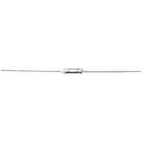
G4A01098C
Description
FUSE, THERMAL, 98°C, 10A, 250V
Manufacturer
THERMODISC
Series
G4r
Datasheet
1.G4A01072C.pdf
(18 pages)
Specifications of G4A01098C
Voltage Rating Vac
250V
Fuse Current
10A
Fuse Terminals
Ferrule
Functioning Temperature
98°C
Holding Temperature
73°C
Fuse Size
14.7 X 4.0mm
Current Rating
10A
Voltage Rating
250V
Lead Free Status / RoHS Status
Lead free / RoHS Compliant


terminals and leads, heating or cooling effect of the terminals and external leads, rate of
temperature rise, air flow, shock, vibration and other environmental and operating conditions
unique to the application.
The product and application being tested will determine the number of cycles that must be run to
determine the maximum “normal” operating temperature. “Overshoot” temperatures should be
included in the determination of the maximum “normal” operating temperature. The overshoot
temperature is often considerably higher than the temperature reached at the moment the
thermostat opens. The conclusion of these tests will provide the maximum “normal” operating
temperature at the thermal cutoff (at maximum anticipated voltage, ambient temperature, etc).
The overshoot temperature seen by the thermal cutoff after the thermal cutoff opens in the
application must also be carefully examined.
Manufacturing tolerances and variations should be carefully considered, and a sufficient number
of units evaluated, to provide a statistical basis on which to determine the operating overshoot
temperatures.
After obtaining the above information, test the product under fault conditions and monitor to
determine that desired fault condition temperatures are not exceeded.
Where there are a variety of fault conditions, (e.g., short-circuited thermostats and transformer
secondaries, locked motor rotors and solenoids, high ambient temperatures, restricted or
blocked airflow, etc.), consideration should be given to multiple fault conditions which could
occur simultaneously during the lifetime of the product, and to faults which may cause localized
overheating in areas away from the TCO.
When the fault conditions have been set up, note the temperature of the dummy cutoff when the
maximum desired temperature limit is reached. At this point the circuit is manually interrupted.
This test should be run several times, in several different units. In some applications, it will not be
possible to “save” the tested item from damage, but only prevent the product from creating an
external fire or electrical hazard. Damaged products should not be retested, since the results may
®
not be the same as with undamaged units. The MICROTEMP
thermal cutoff ratings selected
should be equal to or less than the temperature recorded at the dummy thermal cutoffs at the
time the maximum desired temperature is reached.
CAUTION . . . Excessive overshoot temperatures after the opening of the thermal cutoff may cause
dielectric breakdown of the thermal cutoff and allow reconduction to occur. Functional thermal
cutoffs should be tested to verify proper operation of the thermal cutoffs in the application (see
figure 3).
146
Related parts for G4A01098C
Image
Part Number
Description
Manufacturer
Datasheet
Request
R

Part Number:
Description:
FUSE, THERMAL, 72°C, 10A, 250V
Manufacturer:
THERMODISC
Datasheet:
Part Number:
Description:
FUSE, THERMAL, 93°C, 10A, 250V
Manufacturer:
THERMODISC
Datasheet:
Part Number:
Description:
FUSE, THERMAL, 110°C, 10A, 250V
Manufacturer:
THERMODISC
Datasheet:
Part Number:
Description:
FUSE, THERMAL, 117°C, 10A, 250V
Manufacturer:
THERMODISC
Datasheet:
Part Number:
Description:
FUSE, THERMAL, 121°C, 10A, 250V
Manufacturer:
THERMODISC
Datasheet:
Part Number:
Description:
FUSE, THERMAL, 128°C, 10A, 250V
Manufacturer:
THERMODISC
Datasheet:
Part Number:
Description:
FUSE, THERMAL, 144°C, 10A, 250V
Manufacturer:
THERMODISC
Datasheet:
Part Number:
Description:
FUSE, THERMAL, 152°C, 10A, 250V
Manufacturer:
THERMODISC
Datasheet:
Part Number:
Description:
FUSE, THERMAL, 167°C, 10A, 250V
Manufacturer:
THERMODISC
Datasheet:
Part Number:
Description:
FUSE, THERMAL, 184°C, 10A, 250V
Manufacturer:
THERMODISC
Datasheet:

Part Number:
Description:
Manufacturer:
Omron Corporation
Datasheet:

Part Number:
Description:
Power PCB Relay
Manufacturer:
Omron
Datasheet:
Part Number:
Description:
Power PCB Relay
Manufacturer:
Omron
Datasheet: