SF1200-TAP-E3 Vishay, SF1200-TAP-E3 Datasheet

AVALANCHE DIODE, 1A, 1.2KV, SOD-57

SF1200-TAP-E3

Manufacturer Part Number
SF1200-TAP-E3
Description
AVALANCHE DIODE, 1A, 1.2KV, SOD-57
Manufacturer
Vishay
Datasheet

Specifications of SF1200-TAP-E3

Repetitive Reverse Voltage Vrrm Max
1.2kV
Forward Current If(av)
1A
Forward Voltage Vf Max
3.4V
Reverse Recovery Time Trr Max
75ns
Forward Surge Current Ifsm Max
30A
Diode Type
Fast Recovery
Lead Free Status / RoHS Status
Lead free / RoHS Compliant
SF1200, SF1600
Vishay Semiconductors
MECHANICAL DATA
Case: SOD-57
Terminals: plated axial leads, solderable per MIL-STD-750,
method 2026
Polarity: color band denotes cathode end
Mounting position: any
Weight: approx. 369 mg
www.vishay.com
84
PARTS TABLE
PART
SF1200
SF1600
ABSOLUTE MAXIMUM RATINGS (T
PARAMETER
Reverse voltage = repetitive peak
reverse voltage
Peak forward surge current
Average forward current
Max. pulse energy in avalanche
mode, non repetitive (inductive load
switch off
Junction and storage temperature
range
MAXIMUM THERMAL RESISTANCE (T
PARAMETER
Junction ambient
Ultra-Fast Avalanche Sinterglass Diode
DiodesAmericas@vishay.com, DiodesAsia@vishay.com,
For technical questions within your region, please contact one of the following:
Lead length l = 10 mm, T
I
(BR)R
See electrical characteristics
Half sine wave, V
t
p
= 10 ms, half sine wave
= 400 mA, inductive load
TEST CONDITION
TEST CONDITION
949539
R
amb
TYPE DIFFERENTIATION
thJA
V
V
R
R
amb
= 25 °C, unless otherwise specified)
= 1200 V; I
= 1600 V; I
= 45 k/W
= 25 °C, unless otherwise specified)
R
= V
L
= constant
RRM
FAV
FAV
= 1 A
= 1 A
,
FEATURES
• Very low switching losses
• Glass passivated
• High reverse voltage
• Hermetically
• Compliant to RoHS directive 2002/95/EC and in
• Halogen-free according to IEC 61249-2-21 definition
APPLICATIONS
• Switched mode power supplies
• High-frequency inverter circuits
envelope
accordance to WEEE 2002/96/EC
SF1200
SF1600
PART
SYMBOL
DiodesEurope@vishay.com
R
thJA
sealed
V
V
SYMBOL
T
R
R
j
= V
= V
I
I
= T
FSM
FAV
E
R
RRM
RRM
stg
VALUE
axial-leaded
45
PACKAGE
- 55 to + 175
SOD-57
SOD-57
VALUE
1200
1600
Document Number: 86059
30
10
1
Rev. 1.7, 04-Aug-10
glass
UNIT
K/W
UNIT
mJ
°C
V
V
A
A

Related parts for SF1200-TAP-E3

SF1200-TAP-E3 Summary of contents

Page 1

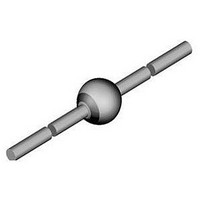
... SF1200, SF1600 Vishay Semiconductors Ultra-Fast Avalanche Sinterglass Diode MECHANICAL DATA Case: SOD-57 Terminals: plated axial leads, solderable per MIL-STD-750, method 2026 Polarity: color band denotes cathode end Mounting position: any Weight: approx. 369 mg PARTS TABLE PART SF1200 SF1600 ABSOLUTE MAXIMUM RATINGS (T ...

Page 2

... V R RRM = 125 °C R RRM j SF1200 l = 100 μA R SF1600 = 0. °C, unless otherwise specified) amb 16464 RRM half sinewave R 45 K/W thJA = 16465 Fig Max. Reverse Power Dissipation vs. Junction Temperature SF1200, SF1600 Vishay Semiconductors SYMBOL MIN. TYP. MAX 3 1250 - - (BR)R V 1650 - - (BR 1000 ...

Page 3

... SF1200, SF1600 Vishay Semiconductors 0.1 1.0 10.0 V – Reverse Voltage ( V ) 16466 R Fig Diode Capacitance vs. Reverse Voltage PACKAGE DIMENSIONS in millimeters (inches): SOD-57 26 (1.024) min. 20543 www.vishay.com For technical questions within your region, please contact one of the following: 86 DiodesAmericas@vishay.com, DiodesAsia@vishay.com, Ultra-Fast Avalanche Sinterglass ...

Page 4

... Vishay product could result in personal injury or death. Customers using or selling Vishay products not expressly indicated for use in such applications their own risk and agree to fully indemnify and hold Vishay and its distributors harmless from and against any and all claims, liabilities, expenses and damages arising or resulting in connection with such use or sale, including attorneys fees, even if such claim alleges that Vishay or its distributor was negligent regarding the design or manufacture of the part ...

Related keywords