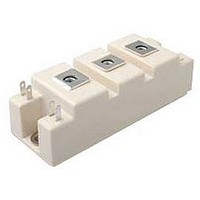
SKM75GB12V SEMIKRON, SKM75GB12V Datasheet
Manufacturer Part Number
SKM75GB12V
Specifications of SKM75GB12V
Dc Collector Current
121A
Collector Emitter Voltage Vces
1.2kV
Collector Emitter Voltage V(br)ceo
940mV
No. Of Pins
7
Package / Case
SEMITRANS 2
Family/system
SEMITRANS
Voltage (v)
1200
Current (a)
75
Chip-type
V-IGBT
Case
SEMITRANS 2
Lead Free Status / RoHS Status
Lead free / RoHS Compliant
SKM75GB12V
SKM75GB12V
Features
• V-IGBT = 6. Generation Trench V-IGBT
• CAL4 = Soft switching 4. Generation
• Isolated copper baseplate using DBC
• UL recognized, file no. E63532
• Increased power cycling capability
• With integrated gate resistor
• Low switching losses at high di/dt
Typical Applications*
• AC inverter drives
• UPS
• Electronic welders
Remarks
• Case temperature limited to
© by SEMIKRON
SEMITRANS
T
T
rel. results valid for T
(Fuji)
CAL-diode
technology (Direct Copper Bonding)
c
op
= 125°C max, recomm.
= -40 ... +150°C, product
GB
j
= 150°
®
2
Absolute Maximum Ratings
Symbol
IGBT
V
I
I
I
V
t
T
Inverse diode
I
I
I
I
T
Module
I
T
V
Characteristics
Symbol
IGBT
V
V
r
V
I
C
C
C
Q
R
t
t
E
t
t
E
R
C
Cnom
CRM
F
Fnom
FRM
FSM
t(RMS)
CES
psc
d(on)
r
d(off)
f
CE
CES
GES
j
j
stg
isol
CE(sat)
CE0
GE(th)
on
off
ies
oes
res
Gint
th(j-c)
G
Rev. 5 – 23.03.2011
T
T
V
V
V
T
t
T
I
V
chiplevel
V
V
V
V
V
V
V
I
V
R
R
di/dt
di/dt
du/dt
µs
Conditions
I
I
AC sinus 50Hz, t = 1 min
Conditions
V
per IGBT
p
C
C
CRM
FRM
j
j
j
terminal
CC
GE
CES
GE
GE
GE
CE
CE
GE
GE
CC
GE
GE
G on
G off
= 10 ms, sin 180°, T
= 25 °C
= 175 °C
= 175 °C
= 75 A
= 75 A
=V
= 1200 V
= 25 V
= 720 V
≤ 20 V
= 15 V
= 15 V
= 0 V
= 0 V
= - 8 V...+ 15 V
= 600 V
= ±15 V
on
off
= 3xI
= 3xI
off
≤ 1200 V
= 1.3
= 1.3
= 3900 A/µs
= 1020 A/µs
CE
= 9000 V/
= 80 °C
, I
Fnom
Cnom
C
= 3 mA
T
T
T
T
T
T
T
T
T
T
T
T
T
f = 1 MHz
f = 1 MHz
f = 1 MHz
T
T
T
T
T
T
c
c
j
c
c
j
j
j
j
j
j
j
j
j
j
j
j
j
j
j
= 125 °C
= 25 °C
= 150 °C
= 25 °C
= 150 °C
= 25 °C
= 150 °C
= 25 °C
= 150 °C
= 150 °C
= 150 °C
= 150 °C
= 150 °C
= 150 °C
= 150 °C
= 25 °C
= 80 °C
= 25 °C
= 80 °C
= 25 °C
min.
5.5
-40 ... 175
-40 ... 175
-40 ... 125
-20 ... 20
Values
12.13
18.27
0.442
1200
4000
typ.
1.85
2.25
0.94
0.88
0.44
10.0
114
225
225
430
200
830
258
388
0.1
4.5
6.7
7.1
87
75
10
97
73
75
32
62
6
20.93
max.
2.30
2.55
1.04
0.98
16.8
0.38
6.5
0.3
Unit
Unit
K/W
m
m
mA
mA
nC
mJ
mJ
°C
°C
°C
nF
nF
nF
µs
ns
ns
ns
ns
V
A
A
A
A
V
A
A
A
A
A
A
V
V
V
V
V
V
1
Related parts for SKM75GB12V
SKM75GB12V Summary of contents
... SKM75GB12V SEMITRANS ® 2 SKM75GB12V Features • V-IGBT = 6. Generation Trench V-IGBT (Fuji) • CAL4 = Soft switching 4. Generation CAL-diode • Isolated copper baseplate using DBC technology (Direct Copper Bonding) • UL recognized, file no. E63532 • Increased power cycling capability • With integrated gate resistor • ...
... SKM75GB12V SEMITRANS ® 2 SKM75GB12V Features • V-IGBT = 6. Generation Trench V-IGBT (Fuji) • CAL4 = Soft switching 4. Generation CAL-diode • Isolated copper baseplate using DBC technology (Direct Copper Bonding) • UL recognized, file no. E63532 • Increased power cycling capability • With integrated gate resistor • ...
... SKM75GB12V Fig. 1: Typ. output characteristic, inclusive R Fig. 3: Typ. turn-on /-off energy = f (I Fig. 5: Typ. transfer characteristic © by SEMIKRON Fig. 2: Rated current vs. temperature I CC'+ EE' ) Fig. 4: Typ. turn-on /-off energy = Fig. 6: Typ. gate charge characteristic Rev. 5 – 23.03.2011 = ...
... SKM75GB12V Fig. 7: Typ. switching times vs Fig. 9: Transient thermal impedance Fig. 11: CAL diode peak reverse recovery current 4 Fig. 8: Typ. switching times vs. gate resistor R Fig. 10: Typ. CAL diode forward charact., incl. R Fig. 12: Typ. CAL diode peak reverse recovery charge Rev. 5 – 23.03.2011 G CC'+EE' ...
... SKM75GB12V SEMITRANS 2 GB This is an electrostatic discharge sensitive device (ESDS), international standard IEC 60747-1, Chapter IX * The specifications of our components may not be considered as an assurance of component characteristics. Components have to be tested for the respective application. Adjustments may be necessary. The use of SEMIKRON products in life support appliances and systems is subject to prior specification and written approval by SEMIKRON. We therefore strongly recommend prior consultation of our staff. © ...
Related keywords
- SKM75GB12V datasheet
- SKM75GB12V data sheet
- SKM75GB12V pdf datasheet
- SKM75GB12V component
- SKM75GB12V part
- SKM75GB12V distributor
- SKM75GB12V RoHS
- SKM75GB12V datasheet download


