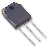
FGA25N120ANTD Fairchild Semiconductor, FGA25N120ANTD Datasheet

FGA25N120ANTD
Specifications of FGA25N120ANTD
Available stocks
Related parts for FGA25N120ANTD
FGA25N120ANTD Summary of contents
Page 1
... Thermal Resistance, Junction-to-Case for Diode θJC R Thermal Resistance, Junction-to-Ambient θJA ©2007 Fairchild Semiconductor Corporation FGA25N120ANTD / FGA25N120ANTD_F109 Rev. B2 Description Using Fairchild's proprietary trench design and advanced NPT technology, the 1200V NPT IGBT offers superior conduction = 2.0V and switching performances, high avalanche ruggedness and easy parallel operation ...
Page 2
... Turn-Off Switching Loss off E Total Switching Loss ts Q Total Gate Charge g Q Gate-Emitter Charge ge Q Gate-Collector Charge gc Notes: (1) Repetitive rating: Pulse width limited by max. junction temperature FGA25N120ANTD / FGA25N120ANTD_F109 Rev. B2 Package Reel Size Tape Width TO- 25°C unless otherwise noted C Test Conditions CES ...
Page 3
... Electrical Characteristics of DIODE Symbol Parameter V Diode Forward Voltage FM t Diode Reverse Recovery Time rr I Diode Peak Reverse Recovery Cur- rr rent Q Diode Reverse Recovery Charge rr FGA25N120ANTD / FGA25N120ANTD_F109 Rev 25°C unless otherwise noted C Test Conditions I = 25A T = 25° 125° 25A T = 25°C ...
Page 4
... Collector-Emitter Voltage, V Figure 3. Saturation Voltage vs. Case Temperature at Variant Current Level 3.0 Common Emitter V = 15V GE 2.5 2.0 1 Case Temperature, T Figure 5. Saturation Voltage vs 40A 25A 12. Gate-Emitter Voltage, V FGA25N120ANTD / FGA25N120ANTD_F109 Rev. B2 Figure 2. Typical Saturation Voltage 120 10V 100 [V] CE Figure 4. Saturation Voltage vs 40A 25A ...
Page 5
... Gate Resistance, R Figure 11. Turn-On Characteristics vs. Collector Current Common Emitter V = ± 15V Ω ° 125 ° 100 Collector Current, I FGA25N120ANTD / FGA25N120ANTD_F109 Rev. B2 (Continued) Figure 8. Turn-On Characteristics vs. Gate Common Emitter 1MHz ° 100 10 10 [V] CE Figure 10. Switching Loss vs. Gate Resistance td(off Ω ...
Page 6
... C C Curves must be derated linearly with increase in temperature 0.01 0 Collector - Emitter Voltage, V Figure 17. Transient Thermal Impedance of IGBT 0 0.2 0.1 0. 0.02 0. FGA25N120ANTD / FGA25N120ANTD_F109 Rev. B2 (Continued) Figure 14. Gate Charge Characteristics 16 14 Eon 12 10 Eoff [A] C Figure 16. Turn-Off SOA 100 50 µ s 100 µ ...
Page 7
... 0.1 0.0 0.4 0.8 1.2 Forward Voltage , V Figure 20. Stored Charge 4000 3000 di/dt = 200A/ µ s 2000 di/dt = 100A/ 1000 Forward Current , I FGA25N120ANTD / FGA25N120ANTD_F109 Rev. B2 (Continued) Figure 19. Reverse Recovery Current ° 125 ° ° 1.6 2.0 [V] F Figure 21. Reverse Recovery Time 300 200 µ ...
Page 8
... Mechanical Dimensions (continued) FGA25N120ANTD /FGA25N!20ANTD_F109 Rev. B2 TO-3PN 9 Dimensions in Millimeters www.fairchildsemi.com ...
Page 9
... TRADEMARKS The following are registered and unregistered trademarks Fairchild Semiconductor owns or is authorized to use and is not intended exhaustive list of all such trademarks. ACEx™ FACT Quiet Series™ ActiveArray™ GlobalOptoisolator™ Bottomless™ GTO™ Build it Now™ HiSeC™ ...


