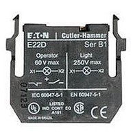
E22D EATON CUTLER HAMMER, E22D Datasheet - Page 16

E22D
Manufacturer Part Number
E22D
Description
Incandescent Light Source Unit
Manufacturer
EATON CUTLER HAMMER
Datasheet
1.E22D.pdf
(60 pages)
14
Cam and contact block selection chart – 3 way adaptor
Circuit configurations. Viewed from front of panel
2 position
Cam II
Explanation of how to use selector switch contact block selection chart
1. Determine the "X O" sequence you require for
your application.
Example:
X = Cicuit closed
O = Circuit open
Note: 16 Illuminated selector switches will accommodate 1 direct voltage or 1 transformer unit with 2 contact blocks.
5 Way adaptor mounting example
Requirement
Hand
X
O
X
X
O
O X
X
O X
X
O X
O X
O X
X
O X
X
O X
O X
O X
X
O X
X
O X
or
Off
O
O
O
O
O
O
O
O
O
O
X
22.5mm Pushbuttons, Indicating Lights and
Selector Switches
E22 Series - Cam and contact block selection charts for selector switches
Hand
Auto
O
O
O
X
X
X
O
Off
O
O
3 position
Cam I
X
O X
X
O X
X
X
O O X
X
O O X
X
O O X
O O X
X
O X
X
O X
O O X
Contact
status
X O O
O O X
X O O
X O O
O X X
The above example uses a 3 position selector switch cam 1 plus mounting adaptor E22BA12
O
X
O O
O O
O O
O O
X
X
O O
O O
Auto
X
X
O
O
O
O
Cam II
X
O X
X
O X
X
X
O O X
X
O O X
X
O O X
O O X
X
O X
X
O X
O O X
Mounting position
5–
With contact block printing facing position 2
O X
O X
O X
O X
X
X
O X
O X
2. Locate the first sequence "X O O" under column
marked Cam I or Cam II, then identify which Cam
and contact is used and in what position it is
assembled.
Example: "X O O" uses Cam I, E22B2, mounting
position 1 (left)
3. Repeat for second sequence "O O X". Do not
mix sequences from Cam I and Cam II.
Example: "O O X" uses Cam I, E22B2, mounting
position 2 (right)
O
O
O
O
O
O
1–
3–
www.eatonelectrical.com
Contact block
mounting position.
Viewed from rear of panel
Left
1
B11
B11
2–
Central
3
4–
Right
2
B1
B11
See note 16
Contact
arrangement
14
24
34
54
52
Contact
arrangement
14
12
14
12
14
14A
24
22
24
22
24
24A
14
12
22
14
12
22
24
4. Assemble contact block(s) to adaptor in the
mounting position selected (two contact blocks
per switch), using the selector switch with the
appropriate cam and switch positions. Cam I has
1 peak, Cam II has 2 peaks, viewed from the rear.
Terminal numbers
These identify the contact block position and
contact function.
Example: 14
The "1" indicates mounting position number 1
(left), "3 & 4" indicates the circuit is N.O.
13
23
33
53
51
13
11
13
11
13
13A
23
21
23
21
23
23A
13
11
21
13
11
21
23
External
link
Contact block
catalogue number
E22B2
E22B2
E22B2
E22B11
13.
Catalogue
number
E22B2
E22B1
E22B11
E22B20
E22B2
E22B1
E22B11
E22B20
E22B11+B1
E22B11+B11
August 2004
PGO4700001U


