GU140X32F-7806A Noritake Company Inc, GU140X32F-7806A Datasheet

VFD MODULE, 140X32

GU140X32F-7806A

Manufacturer Part Number
GU140X32F-7806A
Description
VFD MODULE, 140X32
Manufacturer
Noritake Company Inc
Datasheet

Specifications of GU140X32F-7806A

Resolution
140 X 32
Viewing Area (h X W)
21.61mm X 69.85mm
Supply Current
350mA
Supply Voltage Range
4.75V To 5.25V
Operating Temperature Range
-40°C To +85°C
Character Format
Dot Graphic
Character Type
5x7
Lead Free Status / RoHS Status
Lead free / RoHS Compliant
q
q
q
q
q
q
ELECTRICAL SPECIFICATION
OPTICAL and ENVIRONMENTAL SPECIFICATIONS
SOFTWARE COMMAND SUMMARY
Instruction
Clear Display
Cursor Return Home
Entry Mode Set
Display ON/OFF
Cursor Shift Left
Cursor Shift Right
Display Shift Left
Display Shift Right
Select 4/8 bit interface
Display Luminance
Set CG RAM Addr.
Set DD RAM Addr.
Read BUSY/Addr.
Read Data from RAM
Set Graphic Cursor
Set Area Commands
Write Graphic Image
Set Font / Spacing
Set RS Low
Read Data
Read Cursor Position
Parameter
Power Supply Voltage
Power Supply Current
Logic High Input
Logic Low Input
Logic High Output
Logic Low Output
Parameter
Display Area (XxY mm)
Dot Size/Pitch (XxY mm)
Luminance
Colour of Illumination
Operating Temperature
Storage Temperature
Operating Humidity
Vibration
Shock
Dot Graphic VFD Module
35.5 ±0.5
12.5 ±0.5
NORITAKE ITRON VFD MODULES
140x32 Dot Graphic (4x20 characters)
Single 5V Supply
High Brightness Blue Green Display
Operating Temp -40 C to +85 C
3 Multi Sized Fonts
4/8 Bit Parallel LCD & Serial Interfaces
1.0
11.5
7.5
14.9
1
1.0
1 CN1
Symbol
VCC
ICC
VIH
VIL
VOH
VOL
R/W
33.02
H
H
L
L
L
L
L
L
L
L
L
L
L
L
L
L
L
L
L
L
L
L
L
Value
69.85 x 21.61
0.35 x 0.53 / 0.5 x 0.68
700 cd/m
Blue-Green (Filter for colours)
-40 C to +85 C
-40 C to +85 C
20 to 80% RH @ 25 C (Non-condensing)
10-55-10Hz, all amp 1mm, 30Min X-Y-Z (non-op)
392m/s² (40G) 9mS X-Y-Z (non-operating)
RS
H
H
H
H
H
H
H
L
L
L
L
L
L
L
L
L
L
L
L
L
L
L
L
15.24
Value
5.0VDC +/- 5%
350mADC typ.
0.8VDC min. Vcc max.
0VDC min
3.5VDC min. Vcc max.
0VDC min
2
CN5
01H
02H
04H-07H
08H-0FH
10H
14H
18H
1CH
20H (4Bit) / 30H (8Bit) + luminance
00H-03H (must follow above command)
40H-7FH
80H-E7H
00H-FFH
00H-FFH
F0H + xpos + ypos
F1H + x1 + y1 + x2 + y2 + cmd
where cmd 49H = Invert Area
F1H + x1 + y1 + x2 + y2 + cmd + data
F2H + font style
0FH
FEH
FFH
Typ.
D0-D7
96.0 ±0.5
69.85
2.54
93.0
98.0
2.54
0.6VDC max.
0.6VDC max.
46H = Fill Area
43H = Clear Area
4FH = Set Outline Box
6FH = Clear Outline Box
1
10.16
CN2
D7 Busy = High
Serial Comms. only
Serial Comms. only
Serial Comms. only
6.1
5.5
1
CN4
12.7
Condition
GND=0V
VCC=5V
VCC=5V
VCC=5V
IOH=-10uA
IOL =4mA
The module includes the Vacuum Fluorescent Display glass, VF drivers
and micro-controller ICs with refresh RAM, character generator and
interface logic. The 4/8 bit parallel & serial bi-directional interfaces are
5V TTL/CMOS compatible. The command set is LCD compatible with
extended graphic functions.
7.8
8.4 max.
2.0
42.0
2.5
CHARACTER SET
5x7 & 10x14 Font
NOTE: UDF characters are available using 5x7 font only.
Proportional Mini Font
Parallel Interface type (M68 / i80)
SERIAL MODE
2.5
Copyright 2007 Noritake Itron Corp. Japan
6.5
6.5
Serial / Parallel Selection
1-2 1-2
2-3 2-3 M68
Open
J2
1-2
Link
O
O
X
L
21.61
J6
UDF1
UDF2
UDF3
UDF4
UDF5
UDF6
UDF7
UDF8
UDF1
UDF2
UDF3
UDF4
UDF5
UDF6
UDF7
UDF8
16.7
J4 Mode
J12
3-4
O
O
X
L
60.0
1.6
Sync Serial / Parallel (default)
i80
7-8
O
O
O
L
Dimensions in mm & subject to
Asynchronous Serial
tolerances (±0.2mm unless
Mounting holes 3.2mm dia.
Pin 5 = /WR, Pin 6 = /RD
Pin 5 = R/W, Pin 6 = E
Interface
stated otherwise)
Self Test Mode
Configuration
19200, N, 8, 1
38400, N, 8, 1
9600, N, 8, 1
Signals
GU140x32F-7806A
LCD Font
GU140x32F-7806A
CN1/5 - PARALLEL INTERFACE
Pin 3 can be changed to /RESET or
BUSY terminal and selectable by jumper
J3 (2-3) or J3 (1-2)
Pin
11
13
1
3
5
7
9
All J12 links & J6 should be open for
Parallel operation .
CN1 Pin 3 Function
Nagoya Japan: +81 (0)52-561-9867
Rest Europe: +49 (0)61-0520-9220
Munchen (D): +49 (0)89-3214-290
IUK Doc Ref: 10401 Iss:3 09Oct07
Chicago USA: +1-847-439-9020
Subject to change without notice.
Noritake Sales Office Tel Nos
2 & 3
1 & 2
Itron UK: +44 (0)1493 601144
J3
Canada: +1-416-291-2946
www.noritake-itron.com
CN2 – SERIAL INTERFACE
NC = Do Not Connect
GND
NC*
R/W
Sig
D0
D2
D4
D6
Pin
10
1
2
3
4
5
6
7
8
9
International Font
CONTACT
Async
LINK1
LINK2
/RES
RXD
TXD
Pin
NC
MB
10
12
14
HB
5V
0V
2
4
6
8
/ Reset
Font
Busy
SOUT
VCC
/RES
Sig
SCK
RS
D1
D3
D5
D7
/SS
SIN
SPI
NC
MB
HB
E
5V
0V

Related parts for GU140X32F-7806A

GU140X32F-7806A Summary of contents

Page 1

... Configuration Chicago USA: +1-847-439-9020 7-8 Munchen (D): +49 (0)89-3214-290 Itron UK: +44 (0)1493 601144 O 9600 Rest Europe: +49 (0)61-0520-9220 O 19200 www.noritake-itron.com O 38400 Self Test Mode Subject to change without notice. IUK Doc Ref: 10401 Iss:3 09Oct07 GU140x32F-7806A Async SPI SCK 3 RXD /SS 4 LINK1 SIN 5 0V ...

Page 2

... Additional Serial Data Commands Set the RS line low for the following byte only. Used in serial communications only. Read data at current cursor position. This command is used with serial communications only. Read current cursor position. This command is used with serial communications only. GU140x32F-7806A GU140x32F-7806A ...

Page 3

... NOT read within 40us of sending the command to set either bit mode. >100ns >100ns GU140x32F-7806A X1, Y1 DATA DIRECTION MSB Horizontal Data & Vertical Movement Movement >30ns >25ns >20ns >30ns <25ns >30ns >200ns <65ns >50ns VALID >25ns >20ns >100ns LOWER NIBBLE <120ns tBUSY GU140x32F-7806A DATA DIRECTION tBUSY ...

Page 4

... TTL Synchronous serial communication. DISPLAY TEXT ‘NORITAKE ITRON’ ‘VFD MODULES’ GU140x32F-7806A >250ns >50ns >250ns LOWER NIBBLE Valid STOP START <200us >250ns >250ns <20us MSB LSB MSB LSB >250ns Displaying text using serial communications. GU140x32F-7806A <20us tBUSY STOP tBUSY >250ns ...

Page 5

... Command Structure and Values Copyright 2007 Noritake Co Limited, Japan DISPLAY TEXT ‘NORITAKE ITRON’ ‘VFD MODULES’ DISPLAY TEXT ‘140x32’ GU140x32F-7806A 0,0 0,7 6,7 Cursor Positioning, example of writing 2 characters from cursor position 0,7. Displaying text using the 5x7 font. Displaying text in the large 10x14 font. GU140x32F-7806A ...

Page 6

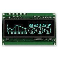
... Displaying graphic images in vertical and horizontal format. Display options with simple graphic text write. Boxes created using the ‘Set Area Outline’ command. Drop Shadows created with the ‘Fill Area’ command. Option ‘Run’ selected with the ‘Invert Area’ command. GU140x32F-7806A ...

Page 7

... TXD OUT MISO OUT MOSI OUT RXD OUT F7H TXD IN MISO IN MOSI IN RXD IN F4H + SETUP TXD OUT HNDSHK DEF H/L CLK EDGE SPEED1 F6H + DATA F8H + SIZE + DATA F5H PEND TXC RXC F7H GU140x32F-7806A D0 SCK I/O D0 SCK OUT D0 SCK IN D0 SPEED0 D0 - ...

Page 8

... The TXC bit is cleared after status read. SERIAL READ F7H The currently buffered data byte can be read with RS high. The host should first check the RXC bit using the PORT STATUS command. After reading the data byte, the RXC bit is cleared. GU140x32F-7806A PARITY0 BAUD1 ...

Related keywords