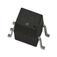
ACPL-M61L-560E Avago Technologies US Inc., ACPL-M61L-560E Datasheet - Page 13

ACPL-M61L-560E
Manufacturer Part Number
ACPL-M61L-560E
Description
Optocoupler (10MBd), LF+T/R+VDE
Manufacturer
Avago Technologies US Inc.
Series
R²Coupler™r
Datasheet
1.ACPL-M61L-500E.pdf
(17 pages)
Specifications of ACPL-M61L-560E
Voltage - Isolation
3750Vrms
Number Of Channels
1, Unidirectional
Current - Output / Channel
10mA
Data Rate
10MBd
Propagation Delay High - Low @ If
46ns @ 6.5mA
Current - Dc Forward (if)
8mA
Input Type
DC
Output Type
Push-Pull, Totem-Pole
Mounting Type
Surface Mount
Package / Case
6-SOIC (0.173", 4.40mm Width) 5 Leads
Number Of Elements
1
Forward Voltage
1.7V
Forward Current
8mA
Output Current
10mA
Isolation Voltage
3750Vrms
Operating Temp Range
-40C to 105C
Pin Count
5
Mounting
Surface Mount
Reverse Breakdown Voltage
5V
Operating Temperature Classification
Industrial
Lead Free Status / RoHS Status
Lead free / RoHS Compliant
Lead Free Status / RoHS Status
Lead free / RoHS Compliant
Optocoupler CMR Performance
The principal protection against common mode noise,
comes from the fundamental isolation properties of the
optocoupler, and this in turn is directly related to the
Input-Output leakage capacitance of the optocoupler.
To provide maximum protection to circuitry connected to
the input or output of the optocoupler the leakage capac-
itance is minimized by having large separation distances
at all points in the optocoupler construction, including
the LED/photodiode interface.
In addition to the optocouplers basic physical construc-
tion, additional circuit design steps mitigate the effects of
common mode noise. The most important of these is the
Faraday shield on the photodetector stage.
A Faraday shield is effective in optocouplers because
the internal modulation frequency (light) is many orders
of magnitude higher than the common mode noise
frequency.
Improving CMR Performance at the Application Level
In an end application it desirable that the optocouplers
common mode isolation be as close as possible to that
indicated in the data sheet specifications. The first step
in meeting this goal is to ensure maximum separation
between PCB interconnects on either side of the opto-
coupler is maintained and that PCB tracks beneath the
optocoupler are avoided.
It is inevitable that a certain amount of CMR noise will be
coupled into the inputs and this can potentially result in
false-triggering of the input. This problem is frequently
observed in devices with input high input impedance.
In some cases this can cause momentary missing pulses
and may even cause input circuitry to latch-up in some
alternate technologies.
The ACPL-x6xL optocoupler family does not have an input
latch-up issue. Even at very high CMR levels such as those
experienced in end equipment level tests (for example
IEC61000-4-4) the ACPL-x6xL series is immune to latch-up
because of the simple diode structure of the LED.
In some cases achieving the rated data sheet CMR per-
formance level is not possible in an application. This is
often because of the practical need to actually connect
the isolator input to the output of a dynamically changing
signal rather than tying the input statically to V
A data sheet CMR “specmanship” issue is often seen with
alternative technology isolators that are based on AC
encoding techniques.
13
DD
or GND.
To address the need to define achievable end application
performance on data sheets, the ACPL-x6xL optocouplers
include an additional typical performance specification
for dynamic CMR in the electrical parameter table. The
dynamic CMR specification indicates the typical achiev-
able CMR performance as the input is being toggled on or
off during a CMR transient.
The logic output the ACPL-x6xL optocouplers is mainly
controlled by LED current level, and since the LED current
features very fast rise and fall times, dynamic noise
immunity is essentially the same as static noise immunity.
Despite their immunity to input latch-up and the
excellent dynamic CMR immunity, ACPL-x6xL opto-
coupler devices are still potentially vulnerable to miss-
operation caused by the LED being turned either on
or off during a CMR disturbance. If the LED status could
be ensured by design, the overall application level CMR
performance would be that of the photodetector. To
benefit from the inherently high CMR capabilities of the
ACPL-x6xL family, some simple steps about operating the
LED at the application level should be taken.
In particular, ensure that the LED stays either on or off
during a CMR transient. Some common design techniques
to accomplish this are:
Keep the LED On:
i) Overdrive the LED with a higher than required forward
Keep the LED Off:
i) Reverse bias the LED during the off state.
ii) Minimize the off-state impedance across the anode
All these methods allow the full CMR capability of the
ACPL-x6xL family to be achieved, but they do have
practical implementation issues or require a compromise
on power consumption.
There is, however, an effective method to meet the goal
of maintaining the LED status during a CMR event with
no other design compromises other than adding a single
resistor.
This CMR optimization takes advantage of the differential
connection to the LED. By ensuring the common mode
impedances at both the cathode and anode of the LED
are equal, the CMR transient on the LED is effectively
canceled. As shown in Figure 11, this is easily achieved by
using two, instead of one, input bias resistors.
current.
and cathode of the LED during the off state.


