ADNS-5050 Avago Technologies US Inc., ADNS-5050 Datasheet - Page 5
ADNS-5050
Manufacturer Part Number
ADNS-5050
Description
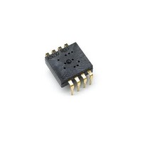
8 DIP SFF Navigation Sensor
Manufacturer
Avago Technologies US Inc.
Datasheet
1.ADNK-5050.pdf
(26 pages)
Specifications of ADNS-5050
Lead Free Status / RoHS Status
Lead free / RoHS Compliant
Lead Free Status / RoHS Status
Lead free / RoHS Compliant
Other names
516-2261
ADNS-5050
ADNS-5050
Available stocks
Company
Part Number
Manufacturer
Quantity
Price
Company:

Part Number:
ADNS-5050
Manufacturer:
RELALTEK
Quantity:
414
Part Number:
ADNS-5050
Manufacturer:
原装AVAGO
Quantity:
20 000


Figure 5. Exploded view drawing.
PCB Assembly Considerations
1. Insert the sensor and all other electrical components
2. Insert the LED into the assembly clip and bend the
3. Insert the LED clip assembly into PCB.
4. Wave solder the entire assembly in a no-wash solder
5. Place the lens onto the base plate.
6. Remove the protective kapton tape from optical
7. Insert PCB assembly over the lens onto the base plate
5
CUSTOMER SUPPLIED BASE PLATE
WITH RECOMMENDED ALIGNMENT
FEATURES PER IGES DRAWING
into PCB.
leads 90 degrees.
process utilizing solder fixture. The solder fixture is
needed to protect the sensor during the solder process.
It also sets the correct sensor-to-PCB distance as the
lead shoulders do not normally rest on the PCB surface.
The fixture should be designed to expose the sensor
leads to solder while shielding the optical aperture
from direct solder contact.
aperture of the sensor. Care must be taken to keep
contaminants from entering the aperture. Recommend
not to place the PCB facing up during the entire mouse
assembly process. Recommend to hold the PCB first
vertically for the kapton removal process.
aligning post to retain PCB assembly. The sensor
aperture ring should self-align to the lens.
ADNS-5200 (LED CLIP)
SENSOR
HLMP-ED80 (LED)
CUSTOMER SUPPLIED PCB
ADNS-5100 (LENS)
8. The optical position reference for the PCB is
9. Install
Figure 6. Block diagram of ADNS-5050 optical mouse sensor.
VDD5
REGO
GND
set by the base plate and lens. Note that the
PCB motion due to button presses must be
minimized to maintain optical alignment.
feature in the top case to press down onto the
PCB assembly to ensure all components are
interlocked to the correct vertical height.
mouse
IMAGE ARRAY
top
OSCILLATOR
LED DRIVE
ADNS-5050
DSP
case. There
MUST
NCS
SCLK
SDIO
NRESET
XY_LED
be
a
Related parts for ADNS-5050
Image
Part Number
Description
Manufacturer
Datasheet
Request
R

Part Number:
Description:
Optical Mouse Sensor,DIP
Manufacturer:
Avago Technologies US Inc.
Datasheet:

Part Number:
Description:
Optical Mouse Sensor,DIP
Manufacturer:
Avago Technologies US Inc.
Datasheet:

Part Number:
Description:
Low Power Wireless LED Sensor
Manufacturer:
Avago Technologies US Inc.
Datasheet:
Part Number:
Description:
USB SoC 3B Optical Sensor
Manufacturer:
Avago Technologies US Inc.
Datasheet:
Part Number:
Description:
Low Power Wireless LED Sensor
Manufacturer:
Avago Technologies US Inc.
Datasheet:
Part Number:
Description:
Optical Mouse Sensor,DIP
Manufacturer:
Avago Technologies US Inc.
Datasheet:

Part Number:
Description:
Trim Lens For ADNS-3530
Manufacturer:
Avago Technologies US Inc.
Datasheet:

Part Number:
Description:
Trim Lens For ADNS-5090
Manufacturer:
Avago Technologies US Inc.
Datasheet:

Part Number:
Description:
BLACK CLIP FOR ADNS-5000
Manufacturer:
Avago Technologies US Inc.
Datasheet:
Part Number:
Description:
Lens For ADNS-7630
Manufacturer:
Avago Technologies US Inc.
Datasheet:

Part Number:
Description:
OPTOCOUPLER GATE DRV 2A 16-SOIC
Manufacturer:
Avago Technologies US Inc.
Datasheet:
Part Number:
Description:
OPTOCOUPLER 2CH 2.5A 16-SOIC
Manufacturer:
Avago Technologies US Inc.
Datasheet:

Part Number:
Description:
OPTOCOUPLER GATE DRV 0.4A 16SOIC
Manufacturer:
Avago Technologies US Inc.
Datasheet:

Part Number:
Description:
OPTOCOUPLER 2.0A 250KHZ 8-DIP
Manufacturer:
Avago Technologies US Inc.
Datasheet:

Part Number:
Description:
OPTOCOUPLER 2.0A 250KHZ GW 8-SMD
Manufacturer:
Avago Technologies US Inc.
Datasheet: