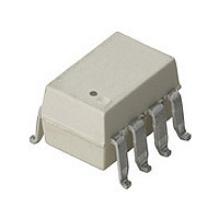
HCPL-260L-560E Avago Technologies US Inc., HCPL-260L-560E Datasheet - Page 20

HCPL-260L-560E
Manufacturer Part Number
HCPL-260L-560E
Description
Optocoupler
Manufacturer
Avago Technologies US Inc.
Datasheet
1.HCPL-060L-000E.pdf
(20 pages)
Specifications of HCPL-260L-560E
No. Of Channels
1
Isolation Voltage
3.75kV
Optocoupler Output Type
Logic Gate
Input Current
15mA
Output Voltage
7V
Opto Case Style
SMD
No. Of Pins
8
Peak Reflow Compatible (260 C)
Yes
Voltage - Isolation
3750Vrms
Number Of Channels
1, Unidirectional
Current - Output / Channel
50mA
Data Rate
15MBd
Propagation Delay High - Low @ If
50ns @ 7.5mA
Current - Dc Forward (if)
20mA
Input Type
DC
Output Type
Open Collector
Mounting Type
Surface Mount, Gull Wing
Package / Case
8-SMD Gull Wing
Number Of Elements
1
Baud Rate
15Mbps
Forward Voltage
1.75V
Forward Current
20mA
Output Current
50mA
Package Type
PDIP SMD
Operating Temp Range
-40C to 85C
Power Dissipation
85mW
Propagation Delay Time
90ns
Pin Count
8
Mounting
Surface Mount
Reverse Breakdown Voltage
5V
Operating Temperature Classification
Industrial
Lead Free Status / RoHS Status
Lead free / RoHS Compliant
Lead Free Status / RoHS Status
Lead free / RoHS Compliant, Lead free / RoHS Compliant
Available stocks
Company
Part Number
Manufacturer
Quantity
Price
Company:
Part Number:
HCPL-260L-560E
Manufacturer:
AVAGO
Quantity:
30 000
Likewise for common-mode transients which occur
when the LED is off (i.e. CMR
if an imbalance between I
I
optocoupler, the transient “signal” may cause the output
to spike below 2 V (which consti tutes a CMR
By using the recommended circuit in Figure 13, good
CMR can be achieved. The balanced I
help equalize I
I
and C
CMR with Other Drive Circuits
CMR performance with drive circuits other than that
shown in Figure 13 may be enhanced by following these
guidelines:
1. Use of drive circuits where current is shunted from the
2. Use of I
Figure 15 shows a circuit which can be used with any
totem-pole-output TTL/LSTTL/HCMOS logic gate. The
buffer PNP transistor allows the circuit to be used with
logic devices which have low current-sinking capability.
It also helps maintain the driving-gate power-supply cur-
rent at a constant level to minimize ground shifting for
other devices connected to the input-supply ground.
When using an open-collector TTL or open-drain CMOS
logic gate, the circuit in Figure 16 may be used. When
using a CMOS gate to drive the optocoupler, the circuit
shown in Figure 17 may be used. The diode in parallel
with the R
LED.
For product information and a complete list of distributors, please go to our website:
Avago, Avago Technologies, and the A logo are trademarks of Avago Technologies in the United States and other countries.
Data subject to change. Copyright © 2005-2010 Avago Technologies. All rights reserved. Obsoletes AV01-0581EN
AV02-0616EN - February 8, 2010
F
LED
equal to or greater than the switching threshold of the
LED in the LED “off” state (as shown in Figures 15 and
16). This is beneficial for good CMR
is modulated from transient coupling through C
LC
.
FH
LED
> 3.5 mA. This is good for high CMR
LP
speeds the turn-off of the optocoupler
and I
LN
to reduce the amount by which
LP
H
and I
, since the output is “high”),
LN
results in a transient
LED
H
.
-setting resistors
H
failure).
L
.
www.avagotech.com
LA
TTL/CMOS
Figure 15. TTL interface circuit.
OPEN-COLLECTOR/
Figure 16. TTL open-collector/open drain gate drive circuit.
OUTPUT LOGIC
Figure 17. CMOS gate drive circuit.
TOTEM-POLE
74L504
GATE)
(ANY
LOGIC GATE)
(OR ANY
OPEN-DRAIN
74HC04
GATE)
(OR ANY
V
74HC00
CC
V
CC
V
CC
2N3906
(ANY PNP)
1N4148
220 Ω
420 Ω
(MAX)
1
2
3
4
R
HCPL-260L
1
2
3
4
HCPL-260L
LED
1
2
3
4
HCPL-260L
LED
LED


