PBRC-2.00BR AVX Corporation, PBRC-2.00BR Datasheet
PBRC-2.00BR
Manufacturer Part Number
PBRC-2.00BR
Description
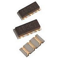
CERAMIC RESONATOR, 2MHZ, SMD
Manufacturer
AVX Corporation
Datasheet
1.PBRC-10.00BR07.pdf
(2 pages)
Specifications of PBRC-2.00BR
Frequency Tolerance
± 0.5%
Resonant Impedance
200ohm
Resonator Case
SMD
No. Of Pins
3
Operating Temperature Range
-20°C To +80°C
Terminal Type
Surface Mount (SMD
Frequency
2MHz
Oscillator Mounting
SMD
Peak Reflow Compatible (260 C)
No
Rohs Compliant
Yes
Leaded Process Compatible
Yes
Resonant Frequency
2MHz


RECOMMENDED LAND
PATTERN FOR PBRC- B/D
DIMENSIONS
PBRC -B, -D Series Chip Resonators
FEATURES
1) Built-in load capacitor
2) High reliability chip resonator
3) Ultra-miniature size is suitable
4) Rectangular shape allows
5) 2000 pcs. per reel
6) Sold in increments of 2000 pcs.
SPECIFICATIONS ( PBRC-
14
Oscillation Frequency
Series Type
Frequency Range
Load Capacitor
Frequency Tolerance
Resonant Impedance
Temperature Characteristics
(-20 to +80°C)
in a ceramic case which can
be reflow soldered and washed
for compact equipment and
high mounting density
easy “pick and place” operation
Built-in Capacitor MHz Band SMT Resonators
(.067)
1.7
(.291)
(.283)
7.4
7. 2
(.098)
2.5
(.059)
1.5
Date Code
(.098)
2.5
(.067)
1.7
Unit: mm (inch)
(.157)
4.0
2.00-2.90MHz
3.00-3.57MHz
3.58-8.00MHz
1
(.236-R0.008)
B/PBRC-
(.098)
2.5
6-R0.2
2.00 to 8.00 MHz
2
PBRC - 4.00 B R
HOW TO ORDER
1 Type: (Piezo Bulk Resonator Chip)
2 Oscillation frequency (MHz)
3 Resonator type:
4 Packaging:
5 Frequency tolerance:
33 pF (typ.)
(.098)
2.5
STANDARD TEST CIRCUIT
2.00 ~ 8.00 MHz
3-1.2 (reference)
±0.5%
±0.3%
1
(.118-.047)
3
B = With capacitor (2.00~20.00MHz)
D = With capacitor (20.01~36.00MHz)
R = Tape and reel
07 = ±0.7% (8.01~20.00MHz)
200 max.
100 max.
30 max.
33pF
= ±0.5% (2.00~8.00MHz)
= ±0.5% (20.01~36.00MHz)
D )
1.0M
C
1
1, 3: Input, Output (no polarity)
2: GND
*t=PBRC B Series: 2.0 max.
R
(PBRC- B)
Tolerances = ±0.3mm
14
PBRC D Series: 1.6 max.
1 2 3 4
MC14069UB
2
(MOTOROLA)
B
V
Resonator
33pF
DD
OUT
C
2
= 5.0V
3
Unit: mm (inch)
7
GND
4
8.01 to 20.00 MHz
150
150
150
10 pF (typ.)
5
±0.7%
±0.1%
Max.
Max.
Max.
STRUCTURE
PAD CONNECTION
STANDARD TEST CIRCUIT
8.01 ~ 36.00 MHz
Terminations: Nickel
Barrier with Gold Flash
Note: Pads 1 and 3 are interchangeable.
Conductive Paste
1. Input
2. Ground
3. Output
ƒ
O
: 2.00 to 36.00 MHz
10pF
1
C
1.0M
1
R
(PBRC- D)
14
1 2 3 4
MC74HC04
Ceramic Element
Electrode
(MOTOROLA)
10 pF (±10)
150
150
150
V
20.01~36
Resonator
10pF
DD
±0.5%
±0.3%
OUT
C
2
2
= 5.0V
D
Alumina
Ceramic Substrate
Max.
Max.
Max.
7
Ceramic Case
GND
3
Related parts for PBRC-2.00BR
Image
Part Number
Description
Manufacturer
Datasheet
Request
R

Part Number:
Description:
RESONATOR CER 8MHZ SMD
Manufacturer:
AVX Corporation
Datasheet:
Part Number:
Description:
RESONATOR CER 4MHZ SMD
Manufacturer:
AVX Corporation
Datasheet:

Part Number:
Description:
RESONATOR CER 4MHZ SMD
Manufacturer:
AVX Corporation
Datasheet:

Part Number:
Description:
RESONATOR CER 3.58MHZ SMD
Manufacturer:
AVX Corporation
Datasheet:
Part Number:
Description:
RESONATOR CER 3.68MHZ SMD
Manufacturer:
AVX Corporation
Datasheet:

Part Number:
Description:
RESONATOR CER 6MHZ SMD
Manufacturer:
AVX Corporation
Datasheet:

Part Number:
Description:
RESONATOR CER 5MHZ SMD
Manufacturer:
AVX Corporation
Datasheet:
Part Number:
Description:
RESONATOR CER 4.91MHZ SMD
Manufacturer:
AVX Corporation
Datasheet:
Part Number:
Description:
RESONATOR CER 7.37MHZ SMD
Manufacturer:
AVX Corporation
Datasheet:
Part Number:
Description:
RESONATOR CER 2MHZ SMD
Manufacturer:
AVX Corporation
Datasheet:
PBRC-2.00BR Summary of contents
Page 1
... PBRC -B, -D Series Chip Resonators Built-in Capacitor MHz Band SMT Resonators FEATURES 1) Built-in load capacitor 2) High reliability chip resonator in a ceramic case which can be reflow soldered and washed 3) Ultra-miniature size is suitable for compact equipment and high mounting density 4) Rectangular shape allows easy “ ...
Page 2
... Tape & Reel Packaging Surface Mountable Chip Resonators PBRC -A, -B, -D Types 2000 pieces per reel with 10 positions open at beginning and end of reel. Leader will be 200mm maximum. TAPE DIMENSIONS ±0.2 ±0.2 ±0.3 ±0.1 3.8 7.8 16.0 7.5 L REEL DIMENSIONS 255 ±1.0 ±0.5 ± ...