3PN216C SUPERIOR ELECTRIC, 3PN216C Datasheet
3PN216C
Manufacturer Part Number
3PN216C
Description
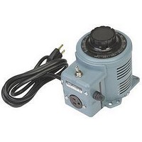
Variable Transformer
Manufacturer
SUPERIOR ELECTRIC
Type
Variabler
Specifications of 3PN216C
Input Voltage
240V
Output Current
3.5A
Knob Rotation
CW / CCW
Transformer Mounting
Bench
Transformer Type
Variable
Secondary Current Nom
3.5A
Supply Voltage
240VAC
Output Voltage
280VAC
Brand/series
Powerstat®/216C Series
Configuration
Housed
Current, Secondary
3.5 A
Frequency
50/60 Hz
Length, Cord
72 "
Mounting Type
Bench
Number Of Outlets
1
Phase
1
Power, Rating
0.84/0.98/0.42 kVA (Constant Current Load), 1.2 kVA (Constant Impedance Load)
Termination
Cord and Plug
Voltage, Primary
240/120 VAC
Voltage, Secondary
0-240/0-280 VAC
No. Of Phases
Single
Primary Voltages
120 / 240V
Power Rating
0.84kVA
Rohs Compliant
Yes
Constant Current Load
3.5A
Current Rating
3.5A
Output Voltage Max
240VAC
Lead Free Status / RoHS Status
Lead free / RoHS Compliant


213709-063 REV D
[95.25]
3-3/4"
[88.90]
3-1/2"
Superior Electric • 28 Spring Lane • Suite 3 • Farmington, CT 06032 USA
[95.25]
3-3/4"
MOUNTING TEMPLATE NO. 1
MOUNTING TEMPLATE NO. 2
HOLE IN PANEL
TO CLEAR 3/8"
CENTER SHAFT
HOLE IN PANEL
TO CLEAR 3/8"
CENTER SHAFT
NOTE: All dimensions are in inches [millimeters]
NOTE: All dimensions are in inches [millimeters]
3 HOLES IN PANEL AT
120° TAPPED FOR 6-32
DIAL MOUNTING SCREWS
[88.90]
STANDARD MOUNTING:
4 SLOTS IN PANEL
AS SHOWN FOR 1/4"
MOUNTING BOLTS
3 HOLES IN PANEL AT
120° TAPPED FOR 6-32
DIAL MOUNTING SCREWS
3-1/2"
4 HOLES IN PANEL AS
SHOWN FOR 1/4"-28
MOUNTING BOLTS
www.superiorelectric.com
[95.25]
3-3/4"
5/8" R
[95.25]
3-3/4"
5/8" R
2-1/2" R
ALTERNATE MOUNTING:
3 SLOTS IN PANEL AT
120° FOR 1/4"
MOUNTING BOLTS
A POWERSTAT Variable Transformer is a precision product packed with care.
When unpacking, examine carefully for any shipping damage. Inspect the brush
contact with particular care. The “Damage and Shortage” Instructions packed
with the unit outline the proper procedure to follow if any parts are damaged
or missing.
NOTE- The unit should be protected from any dust or debris that may be
encountered while drilling holes, installing wiring, etc, during installation.
POWERSTAT Variable Transformer types within this Series have two sets of
mounting holes to facilitate installation in new or existing layouts. Use the set
that is most convenient for the application. All models are designed so that
the same unit can be either bench or back-of-panel mounted as desired. The
units as shipped are arranged for bench mounting. To change to back-of-panel
mounting, proceed as outlined.
Models 3PN116C, 3PN117C, 3PN216C and 3PN217C have a cord and plug
input and a receptacle output, and are usually used as a portable source of
variable a-c voltage. If desired they may be mounted in the same manner as
other manually operated single units.
BENCH OR WALL MOUNTING
1. Using Drilling Template No. 1, locate and drill the desired set of mounting
2. On open construction models (“U” types), loosen the shaft setscrews in the
3. Place the unit in position and insert and fasten ¼” mounting screws.
4. For “U” types, provide a support for the dial. Mount the dial to the support.
5. In addition, on enclosed terminal (“T”) types, remove the terminal cover and
BACK-OF-PANEL MOUNTING
1. Using Drilling Template No.1, locate and drill the desired set of mounting
2. On enclosed models, remove the knob, loosen the shaft setscrews in the
With ordinary care, a POWERSTAT Variable Transformer should require no
servicing except possible replacement of the brush assembly. The brush should
be inspected periodically and replaced if arcing takes place or if it is badly worn.
Because the brush must be of a special material, replace only with a Superior
Electric brush assembly. The assembly is designed to assure perfect contact
of the brush to the commutator regardless of brush position and length of time
in use. Take care to avoid scraping, scratching or marring the commutator
surface. Follow these steps to install a new brush assembly:
1. Unfasten the two brush anchor screws, remove and discard the old brush
2. Insert the new brush assembly. Be sure that the tang on the back of the
3. Raise the brush and place a piece of sandpaper (grit #400 or finer) between
4. While holding the sandpaper in place (flat), rotate the brush through a short
5. Rotate the brush over the full range several times to check for smooth travel
Important connection notes. Please read carefully.
· CONNECTIONS AND RATINGS given in these instructions are those most
· Coil to terminal connections for all POWERSTAT Variable Transformers
· For ambient temperatures between -20°C and +50°C use current ratings
· The connection diagrams are labeled “L” for Line Connections, “B” for Boost
· Clockwise (CW) and counterclockwise (CCW) rotation connections shown
INPUT 120 V.
50/60 Hz
213709-063 REV D
holes (four holes marked “A” or three holes marked “B”).
insulator of the radiator and slide the shaft through so it projects from the
other end of the assembly. Tighten the setscrews.
Attach the knob with its pointer set correctly with respect to the brush location
and the dial indications.
required conduit hole caps. Attach conduit or cable and dress the leads.
Make the necessary connections to the terminal cover.
holes (four holes marked “A” or three holes marked “B”), the three dial
mounting screw holes, and the center shaft hole. Three dial screw holes
must be tapped to accommodate the 6-32 screws supplied. Maximum panel
thickness is 5/8” for open (“U” type) models.
insulator of the radiator and slide the shaft through so it projects from the
other end of the assembly. Tighten the setscrews. Maximum panel thickness
for enclosed models is 5/16”.
assembly.
brush assembly goes under the overhang at the rear of the radiator slot.
Replace and tighten the brush anchor screws.
the brush and the commutator with the abrasive side against the brush.
arc about four times. Remove the sandpaper and blow out any remaining
carbon particles.
and to be sure the brush fits flat to the commutator over the full range.
commonly used. In addition, all ganged units may be connected so that
the units operate electrically independent on a common shaft. When this is
desired, connections and ratings for the individual models may be obtained
from the RATINGS CHART and CONNECTION DIAGRAMS of the single
unit.
included in these instructions are given in Figures B, C, and D.
given in the charts. Figure E shows the output current de-rating required
above 50°C.
Connections and “S” for Step-Up Connections.
in the tables and diagrams are for motor driven units and units with the knob
on the radiator end. For connections with the knob on the base end, use
the shown CCW connection for CW operation, and shown CW connection
for CCW operation.
40 VAC TYPES
LOWER
RAISE
FIGURE B
VIEWED FROM
RADIATOR END
1
2
3
MANUALLY OPERATED ASSEMBLIES
instructions
DRIVE MOTOR
FARMINGTON, CT 06032 USA
MOTOR DRIVE WIRING
28 SPRING LANE • SUITE 3
www.superiorelectric.com
LIMIT SWITCH
INSTALLATION
120 VAC TYPES
LOWER
FIGURE G
INSPECTION
C
RADIATOR END
FIGURE C
SINGLE UNITS
VIEWED FROM
POWERSTAT
NC
NO
116CU-40 / 116C / 117C / 216C and 217C Series
RESISITOR
LIMIT SWITCH
UPPER
C
OPERATION and MAINTENANCE
240 VAC TYPES
NC
NO
VARIABLE TRANSFORMERS
RADIATOR END
FIGURE D
VIEWED FROM
CONNECTIONS AND RATINGS
WITH POWERKOTE
Telephone and Fax Numbers
Telephone
Fax
Customer Service 860-585-4500, Menu # 2
Product Application 860-585-4500, Menu # 3
INSTALLATION
MAINTENANCE
† Cord-and-Plug units supplied with these fuses
ECN 95830
BASIC UNIT TYPE
100
80
60
40
20
860-585-4500
860-582-3784
0
for
104°F 122°F
40°C
116CU-40
116C
117C
216C
217C
RECOMMENDED FUSE (AMPERES)
3. Mount the dial on the front of the panel. Place the POWERSTAT Variable
4. Attach the knob with the pointer set correctly with respect to the brush location
BENCH OR WALL MOUNTING
BACK-OF-PANEL MOUNTING
Motor-driven POWERSTAT Variable Transformer types within this Series, both
single units and ganged assemblies, may be bench or wall mounted in the same
manner as manually operated ganged assemblies. Three-gang assemblies,
however, have three side brackets requiring six bolts.
· For the Step-Up Connections the tables show maximum output current rating
· Motor drive wiring is shown in Figure G.
· Fuses are recommended on all units as shown (§) and are supplied on
· COMMON shown in the connection diagrams is used as third leg in 3-
· Cord-and-plug models 3PN116C and 3PN216C are wired in the Boost “B”
50°C
A. On Standoffs
B. On Side Brackets
Transformer in the position behind the panel and insert and tighten ¼”
mounting screws.
and dial indications.
for output voltages up to 125% of the input voltage, and maximum KVA at
maximum output voltage. The output current must be reduced according to
the curve in Figure F for output voltages greater then 125% of input voltage.
Maximum KVA may be calculated using the rating curve in Figure F for
voltages less then maximum.
cord-and-plug 3PN116C (10 ampere), 3PN117C (15 ampere), 3PN216C
(4 ampere) and 3PN217C (8 ampere) models. For all other models, see
Figure H for recommended fuse ratings.
phase open delta, or neutral in single-phase 3-wire and 3-phase 4-wire wye
configurations. COMMON is not used in single-phase 2-wire or 3-phase 3-
wire wye configurations. Jumper(s) provided in standard common position
should be moved or removed as required.
Connection when shipped.
AMBIENT TEMPERATURE
Whenever unusual mechanical or electrical difficulties are encountered in
the operation or installation of your POWERSTAT Variable Transformer,
consult Superior Electric.
FIGURE E
1. Using Drilling Template No. 2, locate and drill the four mounting
2. Remove the knob and dial, loosen the shaft setscrews in the insulator
3. Place the unit in position and insert and fasten ¼”-28 mounting bolts
4. Provide a support for the dial. Mount the dial to the support. Attach
1. Using Drilling Template No. 3, locate and drill the proper set of mounting
2. Insert two ¼” mounting screws at one end of the assembly and screw
3. Place the unit in position. Insert the other ¼” screws and tighten all
1. Using Drilling Template No. 2, locate and drill the four mounting screw
2. Secure the dial in place. Place the assembly in position behind the
3. Provide a support in the form of a bench or cradle for the assembly
4. Attach the knob with the pointer set correctly with respect to the brush
140°F
60°C
®
FIGURE C
holes.
of each radiator and adjust the shaft so it projects from the radiator
end of the assembly. Turn all of the radiators fully counterclockwise
and tighten the shaft setscrews. Check to see that all brushes are in
alignment.
into the standoffs. Maximum bolt length is the panel thickness plus
3/8”.
the knob with its pointer set correctly with respect to the brush location
and the dial indications.
holes.
down part way.
screws.
holes, the three dial mounting screw holes and the center shaft hole.
The dial screw holes must be tapped to accommodate the 6-32 screws
supplied. Maximum panel thickness is 3/4”.
panel and insert and tighten ¼”-28 mounting screws. Mounting screw
length should be the panel thickness plus 3/8”.
location and the dial indications.
COILS
116C / 117C
216C / 217C
116CU-40
FIGURE H
158°F
70°C
TYPE
CONSTANT
CURRENT
LOAD
176°F
80°C
10†
25
15
4†
5
REPLACEMENT BRUSH ASSEMBLIES
MOTOR-DRIVEN ASSEMBLIES
194°F
90°C
Toll-Free (in USA and Canada only)
Telephone
Fax
Customer Service
Product Application 1-800-787-3532, Menu # 3
GANGED ASSEMBLIES
IMPEDANCE
CONSTANT
LOAD
15†
30
15
8†
5
065431-004
065431-001
065431-002
PART NO.
OPERATION IN “STEP-UP” CONNECTION
®
1-800-787-3532
1-800-821-1369
1-800-787-3532, Menu # 2
The right to make engineering refinements on
all products is reserved. Dimensions and other
details are subject to change.
BRUSH ASSEMBLY
FIGURE F
Number
Model
15ME
30ME
60ME
Prefix
7ME
FIGURE A
Motor Driven Prefix
RB116C/RB117C
RB216C/RB217C
DESCRIPTION
shown below:
RB116C-40
FIGURE I
Full Travel (seconds)
Operating Time for
60 Hz
15
30
60
7
Printed in USA
50 Hz
18
36
72
8
Related parts for 3PN216C
Image
Part Number
Description
Manufacturer
Datasheet
Request
R

Part Number:
Description:
Replacement Brush For Superior Electric 126 Series Transformers
Manufacturer:
SUPERIOR ELECTRIC
Datasheet:

Part Number:
Description:
Variable Transformer
Manufacturer:
SUPERIOR ELECTRIC
Datasheet:

Part Number:
Description:
Variable Transformer
Manufacturer:
SUPERIOR ELECTRIC
Datasheet:
Part Number:
Description:
Variable Transformer
Manufacturer:
SUPERIOR ELECTRIC
Datasheet:

Part Number:
Description:
Variable Transformer
Manufacturer:
SUPERIOR ELECTRIC
Datasheet:

Part Number:
Description:
Variable Transformer
Manufacturer:
SUPERIOR ELECTRIC
Datasheet:

Part Number:
Description:
Variable Transformer
Manufacturer:
SUPERIOR ELECTRIC
Datasheet:
Part Number:
Description:
Variable Transformer
Manufacturer:
SUPERIOR ELECTRIC
Datasheet:
Part Number:
Description:
Variable Transformer
Manufacturer:
SUPERIOR ELECTRIC
Datasheet:
Part Number:
Description:
STABILINE Full Range Regulator Microprocessor Control, 1 Channel
Manufacturer:
SUPERIOR ELECTRIC

Part Number:
Description:
Surge Suppressor
Manufacturer:
SUPERIOR ELECTRIC
Datasheet:
Part Number:
Description:
Surge Suppressor
Manufacturer:
SUPERIOR ELECTRIC
Datasheet:
Part Number:
Description:
Surge Suppressor
Manufacturer:
SUPERIOR ELECTRIC
Datasheet:
Part Number:
Description:
#21U TYPE 21-117 VARIAC 5 AMMP 120V INPUT TRANSISTOR
Manufacturer:
SUPERIOR ELECTRIC
3PN216C Summary of contents
Page 1
... COMMON is not used in single-phase 2-wire or 3-phase 3- wire wye configurations. Jumper(s) provided in standard common position should be moved or removed as required. · Cord-and-plug models 3PN116C and 3PN216C are wired in the Boost “B” Connection when shipped. VIEWED FROM VIEWED FROM 104° ...
Page 2
... Model Numbers Current Load Input Output Jumper Freq. Max. Max. Manually Motor Driven Conn (Hz) Amps KVA Operated (See Fig. I) Diag. CCW CCW CCW 3PN216C 17 1-6 1-3 50/60 3.5 0.42 216CU ME216CU 4-7 3-4 2 216CT ME216CT 3PN217C 19 217CU ME217CU 13 217CT ME217CT 116CU-2 ME116CU-2 ...