ADXL203EB Analog Devices Inc, ADXL203EB Datasheet - Page 9
ADXL203EB
Manufacturer Part Number
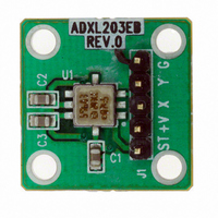
ADXL203EB
Description
±1.7g Dual-Axis IMEMS Accelerometer Evaluation Board
Manufacturer
Analog Devices Inc
Series
iMEMS®r
Specifications of ADXL203EB
Silicon Manufacturer
Analog Devices
Application Sub Type
Accelerometer - Dual-Axis
Kit Application Type
Sensing - Motion / Vibration / Shock
Silicon Core Number
ADXL203
Sensor Type
Accelerometer, 2 Axis
Sensing Range
±1.7g
Interface
Analog
Sensitivity
1000mV/g
Voltage - Supply
3 V ~ 6 V
Embedded
No
Utilized Ic / Part
ADXL203
Lead Free Status / RoHS Status
Contains lead / RoHS non-compliant
Other names
Q1875695


THEORY OF OPERATION
The ADXL103/ADXL203 are complete acceleration measure-
ment systems on a single, monolithic IC. The ADXL103 is a
single-axis accelerometer, and the ADXL203 is a dual-axis
accelerometer. Both parts contain a polysilicon surface-
micromachined sensor and signal conditioning circuitry to
implement an open-loop acceleration measurement architecture.
The output signals are analog voltages proportional to acceleration.
The ADXL103/ADXL203 are capable of measuring both positive
and negative accelerations to at least ±1.7 g. The accelerometer
can measure static acceleration forces such as gravity, allowing
it to be used as a tilt sensor.
The sensor is a surface-micromachined polysilicon structure
built on top of the silicon wafer. Polysilicon springs suspend the
structure over the surface of the wafer and provide a resistance
against acceleration forces. Deflection of the structure is measured
using a differential capacitor that consists of independent fixed
plates and plates attached to the moving mass. The fixed plates
are driven by 180° out-of-phase square waves. Acceleration deflects
the beam and unbalances the differential capacitor, resulting in
an output square wave whose amplitude is proportional to
acceleration. Phase-sensitive demodulation techniques are then
used to rectify the signal and determine the direction of the
acceleration.
X
Y
OUT
OUT
= 2.5V
= 3.5V
PIN 8
Figure 23. Output Response vs. Orientation
(Not to Scale)
X
Y
X
Y
TOP VIEW
OUT
OUT
OUT
OUT
Rev. C | Page 9 of 12
PIN 8
PIN 8
= 1.5V
= 2.5V
= 3.5V
= 2.5V
The output of the demodulator is amplified and brought off-chip
through a 32 kΩ resistor. At this point, the user can set the
signal bandwidth of the device by adding a capacitor. This
filtering improves measurement resolution and helps prevent
aliasing.
PERFORMANCE
Rather than using additional temperature compensation circuitry,
innovative design techniques have been used to ensure that high
performance is built in. As a result, there is essentially no
quantization error or non-monotonic behavior, and temperature
hysteresis is very low (typically less than 10 mg over the −40°C
to +125°C temperature range).
Figure 11 shows the 0 g output performance of eight parts
(x and y axes) over a −40°C to +125°C temperature range.
Figure 14 demonstrates the typical sensitivity shift over
temperature for V
V
typically better than ±1% over temperature at V
S
= 5 V but is still very good over the specified range; it is
PIN 8
X
Y
EARTH'S SURFACE
OUT
OUT
= 2.5V
= 1.5V
X
Y
OUT
OUT
S
= 2.5V
= 2.5V
= 5 V. Sensitivity stability is optimized for
ADXL103/ADXL203
S
= 3 V.
Related parts for ADXL203EB
Image
Part Number
Description
Manufacturer
Datasheet
Request
R

Part Number:
Description:
Analog MCU Evaluation Board
Manufacturer:
Analog Devices Inc
Datasheet:
Part Number:
Description:
Inertial Sensor Evaluation System
Manufacturer:
Analog Devices Inc
Datasheet:
Part Number:
Description:
Manufacturer:
Analog Devices Inc
Datasheet:
Part Number:
Description:
Manufacturer:
Analog Devices Inc
Datasheet:
Part Number:
Description:
Manufacturer:
Analog Devices Inc
Datasheet:
Part Number:
Description:
Manufacturer:
Analog Devices Inc
Datasheet:
Part Number:
Description:
Manufacturer:
Analog Devices Inc
Datasheet:
Part Number:
Description:
Manufacturer:
Analog Devices Inc
Datasheet:
Part Number:
Description:
Manufacturer:
Analog Devices Inc
Datasheet:
Part Number:
Description:
Manufacturer:
Analog Devices Inc
Datasheet:
Part Number:
Description:
Manufacturer:
Analog Devices Inc
Datasheet:
Part Number:
Description:
Manufacturer:
Analog Devices Inc
Datasheet:
Part Number:
Description:
Manufacturer:
Analog Devices Inc
Datasheet: