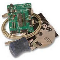
EB194 MATRIX, EB194 Datasheet - Page 9

EB194
Manufacturer Part Number
EB194
Description
MULTI PROGRAMMER KIT, AVR, ATMEL
Manufacturer
MATRIX
Datasheet
1.EB194.pdf
(14 pages)
Specifications of EB194
Mcu Supported Families
Atmel AVR
Programmer Type
Multiprogrammer
Development Tool Type
AVR Multiprogrammer
Tool / Board Application
Programming / Developing
Tool / Board
RoHS Compliant
Ic Product Type
In-Circuit Programmer
Features
E-Blocks Compatible, Low Cost, Used As A Programmer And As A Development Board, 4 Full I/O Ports
Rohs Compliant
Yes
Power Supply
The board can be powered from an unregulated 14V supply. The regulation circuitry will withstand
unregulated 20V as a maximum input voltage and 7V as a minimum. If you are using a DC power
supply then you should use a 14V setting. Power can be connected using the 2.1mm power jack
(positive outer), or the screw terminal connectors J1, J2. The two “+V OUT” screw terminals are
supplied for powering other E-blocks™, supplying approximately +5V. The regulator will supply up
to 400mA via all outputs. LED D3 will indicate that power is connected to the board and that the
voltage regulation circuitry is fully functional.
Please note connector J4 is directly connected to the J1 screw terminal pin 1 labelled ‘+14V’,
therefore any voltage input to J4 will also be available direct from pin 1 of J1. This means that
‘+14V’ will not necessarily be +14V
Note
Remember that other E-blocks will have to receive +5V by placing a connecting wire from the “+V
Out” screw terminal of the Multiprogrammer to the “+V” screw terminal of each E-Block that
requires a voltage.
Programming - Hardware
The AVR® Board connects to a personal computer via the AVRISP or compatible device. The
AVRISP requires +5V and ground connection these are all provided on the board via the
programming header J3.
The following diagram shows the pin-out of the connector J3. The pin-out is the standard pin-out
as used by AVRISP.
By default the pins RB5, RB6, and RB7 are used to program the slave AVR® device. These are
the pins that provide the programming functions MOSI, MISO and SCK respectively. Due to the
nature of programming it is recommended that programming pins have clean signals when
programming, therefore there are 120-Ohm resistors between these pins and the associated Port
B pins. This is achieved by placing the 3-way link block in the “DEFAULT” mode for J9, J10 and
J11. This provides the adequate protection whilst programming.
If problems occur in the programming sequence we recommend completely removing the 3-way
jumper link on J9, J10 and J11. This allows MISO, MOSI and SCK to be completely clean whilst
Copyright © 2004 Matrix Multimedia Limited
Figure showing Pin-Out of ISP header J3
MISO
/RESET
SCK
3
1 2
5 6
4
Matrix Multimedia Atmel AVR® Board
VCC
MOSI
GND
EB19430
Page 9


