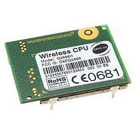
Q2686H WAVECOM, Q2686H Datasheet - Page 57

Q2686H
Manufacturer Part Number
Q2686H
Description
MODULE, GSM/GPRS, QUAD BAND
Manufacturer
WAVECOM
Datasheet
1.Q2686H.pdf
(89 pages)
Specifications of Q2686H
Mcu Supported Families
ARM9
Kit Features
GSM/GPRS Class 10 Quad Band Version, 32MB Of Bursted Flash Memory, 8MB Of SRAM
Tool / Board Applications
Wireless Communication
Development Tool Type
CPU
Lead Free Status / RoHS Status
Lead free / RoHS Compliant
3.16
This signal is used to force a reset procedure by providing low level for at least
200μs. This signal must be considered as an emergency reset only. A reset
procedure is already driven by the internal hardware during the power-up
sequence.
This signal may also be used to provide a reset to an external device (at power-
up only). If no external reset is necessary, this input may be left open. If used
(emergency reset), it must be driven by an open collector or an open drain.
The Wireless CPU
low.
CAUTION: This signal should only be used for “emergency” resets.
An Operating System reset is to be preferred to a hardware reset.
Reset sequence:
To activate the "emergency" reset sequence, the ~RESET signal must be set to
low for 200μs minimum. As soon as the reset is completed, the AT interface
answers "OK" to the application.
At power-up, the ~RESET time (Rt) is carried out after switching ON the
Wireless CPU
supervisor.
The ~RESET time is provided by the internal RC component. To keep the same
time, it is not recommended to connect another R or C component on the
~RESET signal. Only a switch or an open drain gate is recommended.
Ct is the cancellation time required for the Wireless CPU
Ct is automatically carried out by the Q2686 Wireless CPU
reset.
This document is the sole and exclusive property of WAVECOM. Not to be distributed or divulged without
prior written agreement.
WM_PRJ_Q2686_PTS_001-007
Wireless CPU
~RESET
STATE OF
THE
Reset Signal (~RESET)
®
®
Wireless
Rt = Min
. It is generated by the internal Q2686 Wireless CPU
READY
or Typ
CPU
confidential ©
®
®
remains in reset mode as long as the ~RESET signal is held
2
Figure 9: Reset sequence waveform
= 40ms
1
:200μs
RESET mode
I
BB+RF
40mA
=20 to
Ct = Typ:34ms
Wireless CPU
without loc update
SIM and network
I
BB+RF
dependent
Q2686 Wireless CPU
<120mA
ON
®
Q2686 initialization.
®
®
after a hardware
AT answers “OK”
Wireless CPU
Interfaces
READY
®
voltage
March 6, 2007
Page: 56 / 87
®
®


