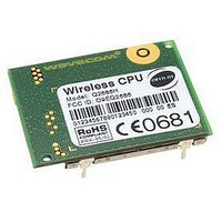
Q2686H WAVECOM, Q2686H Datasheet - Page 9

Q2686H
Manufacturer Part Number
Q2686H
Description
MODULE, GSM/GPRS, QUAD BAND
Manufacturer
WAVECOM
Datasheet
1.Q2686H.pdf
(89 pages)
Specifications of Q2686H
Mcu Supported Families
ARM9
Kit Features
GSM/GPRS Class 10 Quad Band Version, 32MB Of Bursted Flash Memory, 8MB Of SRAM
Tool / Board Applications
Wireless Communication
Development Tool Type
CPU
Lead Free Status / RoHS Status
Lead free / RoHS Compliant
3.5
3.6
3.7
3.8
3.9
3.10
3.11
3.12
3.13
3.14
3.15
3.16
3.17
3.18
3.19
3.20
3.21
3.22
This document is the sole and exclusive property of WAVECOM. Not to be distributed or divulged without
prior written agreement.
WM_PRJ_Q2686_PTS_001-007
3.4.2
3.8.1
3.11.1
3.11.2
3.11.3
3.13.1
3.13.2
3.13.3
3.13.4
3.14.1
3.19.1
3.21.1
3.4.1.4
3.4.2.1
3.4.2.2
3.11.1.1
3.11.1.2
3.11.1.3
3.11.1.4
3.11.2.1
3.11.2.2
3.11.3.1
3.11.3.2
3.11.3.3
3.14.1.1
3.14.1.2
Keyboard Interface ................................................................................ 34
Main Serial Link (UART1) ...................................................................... 35
Auxiliary Serial Link (UART2) ................................................................ 37
SIM Interface ........................................................................................ 38
General Purpose Input/Output .............................................................. 40
Analog to Digital Converter ................................................................... 42
Analog Audio Interface ......................................................................... 43
Buzzer Output ...................................................................................... 47
Battery Charging Interface .................................................................... 48
ON / ~OFF signal .................................................................................. 51
BOOT Signal ......................................................................................... 55
Reset Signal (~RESET) .......................................................................... 56
External Interrupt.................................................................................. 58
VCC_2V8 and VCC_1V8 Output ............................................................. 59
BAT-RTC (Backup Battery).................................................................... 60
FLASH-LED Signal ................................................................................ 61
Digital Audio Interface (PCM)................................................................ 63
USB 2.0 Interface.................................................................................. 66
I2C Bus ......................................................................................... 32
General Description....................................................................... 38
Microphone Inputs........................................................................ 43
Common Speaker Output Characteristics...................................... 45
Speaker Outputs ........................................................................... 45
Ni-Cd / Ni-Mh Charging Algorithm ................................................ 48
Li-Ion Charging Algorithm ............................................................. 49
Controlled Pre-charging Hardware ................................................ 50
Temperature Monitoring ............................................................... 50
Operating Sequences .................................................................... 51
Interface Description ..................................................................... 60
Description ................................................................................... 63
SPI2 Bus ................................................................................. 31
I²C Waveforms ........................................................................ 32
I²C Bus Pin-out ....................................................................... 33
Common Microphone Input Characteristics ............................ 43
Main Microphone Inputs (MIC2) ............................................. 43
Auxiliary Microphone Inputs (MIC1)........................................ 44
Microphone Electrical Characteristics...................................... 44
Differential Connection ............................................................ 45
Single-ended Connection ........................................................ 45
Speaker 2 Outputs .................................................................. 45
Speaker 1 Outputs .................................................................. 46
Speaker Power Output ............................................................ 46
Power-ON ............................................................................... 51
Power-OFF.............................................................................. 54
confidential ©
Q2686 Wireless CPU
March 6, 2007
Page: 8 / 87
®


