Q2686H DK WAVECOM, Q2686H DK Datasheet - Page 23
Q2686H DK
Manufacturer Part Number
Q2686H DK
Description
KIT. DEV, Q2686H, GSM/GPRS
Manufacturer
WAVECOM
Datasheet
1.Q2686H_DK.pdf
(66 pages)
Specifications of Q2686H DK
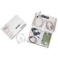
Kit Contents
Development Kit Q26 Board, Wireless CPU Soldered, SMA/FME Antenna, Adapter, RS232/USB Cable, CDROM
Development Tool Type
Development Kit
Kit Contents Descriptive
2x Q2686H Modules, 1x
Lead Free Status / RoHS Status
Lead free / RoHS Compliant


* If the special solder, J103, is not soldered, an external power supply must be used. It is recommended to
use both VBATT and VBAT always together.
5.2
The J100 connector has three contacts:
(1): This value has to be maintained during the burst (with 2.0A Peak in GSM, GPRS, and EDGE mode)
(2): Maximum operating Voltage Stationary Wave Ratio (VSWR) is 2:1.
5.3
This signal acts as an input (ADC) in the Wireless CPU.
battery.
For more information, refer to either document [3] or [6].
J100:2-3 also allows simulation of the temperature level by a sensor inside the
This document is the sole and exclusive property of Wavecom. Not to be distributed or divulged without
prior written agreement.
WM_BBD_Q26_UGD_001-004
•
•
External Supply
J100:1-2: for the power supply.
J100:2-3: refer to section 5.3
BAT-TEMP
BAT-TEMP
©Confidential
VBATT
BAT-TEMP
3
LED
Light ON
Light OFF*
GND
1,2
Table 3: Electrical Characteristics
Table 4: Electrical Characteristics
2
Figure 4: Power supply voltage
(*) Refer to doc [2] or doc [5]
Table 2: LED of "VBAT"
1
VBATT
V
3.2v
V
0
min
min
VBATT
ON
Can be ON OFF
Development Kit Q2686 and Q2687
V
3.6v
V
-
nom
nom
VBAT
ON
V
(*)
V
2v
max
max
September 11, 2006
Power Supply
Page: 22/ 64
Related parts for Q2686H DK
Image
Part Number
Description
Manufacturer
Datasheet
Request
R

Part Number:
Description:
MODULE, GSM/GPRS, QUAD BAND
Manufacturer:
WAVECOM
Datasheet:
