CDB3318 Cirrus Logic Inc, CDB3318 Datasheet
CDB3318
Specifications of CDB3318


Related parts for CDB3318


CDB3318 Summary of contents
Page 1
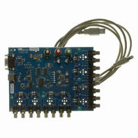
... Inputs USB/RS232 PC Interface http://www.cirrus.com Description The CDB3318 evaluation board is an excellent means for evaluating the CS3318 analog volume control. Eval- uation requires an analog signal source and analyzer, power supplies, and a Windows PC compatible computer. Standard RCA phono jacks are provided to easily inter- face external analog signals with the evaluation board. Each of the CS3318’ ...
Page 2
... Figure 7.Block Diagram ............................................................................................................................... 9 Figure 8.CS3318 ....................................................................................................................................... 10 Figure 9.Analog Inputs and Outputs ......................................................................................................... 11 Figure 10.Serial Control / Power ............................................................................................................... 12 Figure 11.Silkscreen Top .......................................................................................................................... 13 Figure 12.Top Side Copper Layer ............................................................................................................. 14 Figure 13.Bottom Side Copper Layer ........................................................................................................ 15 LIST OF TABLES Table 1. System Connections ..................................................................................................................... 8 Table 2. On-Board Switches ....................................................................................................................... 8 Table 3. System Headers ............................................................................................................................ 8 2 CDB3318 DS693DB2 ...
Page 3
... The AD0, ENOut, and MUTE signals are re-driven versions of these signals as present directly on their respective I/O pins on the CS3318. This header may be used to connect the serial control signals be- tween 2 or more CDB3318’s (out of J89 on one and in to J17 on another) for multiple CS3318 I²C serial control evaluation. ...
Page 4
... CCLK signals, as well as its AD0, ENOut, and MUTE signals. All of the signals re-driven versions of those present directly on their respective I/O pins on the CS3318. This header may be used to connect the serial control signals between 2 or more CDB3318’s (out of J88 on one and in to J17 on another) for multiple CS3318 SPI serial control evaluation. ...
Page 5
... Step-by-step instructions for using the FlexGUI are provided as follows: 1. Download and install the FlexGUI software from www.cirrus.com/msasoftware. 2. Connect the CDB3318 to a host PC using the supplied USB cable or a 9-pin serial cable. 3. Apply positive power, negative power, and ground to the VA+, VA-, and GND binding posts respectively. ...
Page 6
... The software is only capable of addressing the CS3318 at its default address. If the CS3318’s individual address is changed, the software will loose communication with the device until it is reset, thereby returning to its default address. See the CS3318 datasheet for more information about the device’s individual ad- dress. 6 Figure 2. Register Maps Tab CDB3318 DS693DB2 ...
Page 7
... B r -90 A -100 -110 -120 -130 -140 -150 -160 -170 -180 2k 5k 10k 20k 20 CDB3318 = 20 pF RMS IN 200m 300m 400m 500m 600m 700m 900m Vrms Figure 4. THD+N vs. Amplitude 50 100 200 500 Figure 6. Crosstalk = 1 kHz 10k ...
Page 8
... CS3318 J52 J67 When no shunt is present across the header’s pins, its respective output J68 connector will be AC coupled to the associated output of the CS3318 J84 J85 Table 3. System Headers CDB3318 . Switch Function Header Function . . . DS693DB2 . ...
Page 9
... CDB BLOCK DIAGRAM DS693DB2 CDB3318 9 ...
Page 10
... CDB SCHEMATICS 10 CDB3318 DS693DB2 ...
Page 11
... DS693DB2 CDB3318 11 ...
Page 12
... CDB3318 DS693DB2 ...
Page 13
... CDB LAYOUT DS693DB2 CDB3318 13 ...
Page 14
... CDB3318 DS693DB2 ...
Page 15
... DS693DB2 CDB3318 15 ...
Page 16
... Cirrus Logic, Cirrus, and the Cirrus Logic logo designs are trademarks of Cirrus Logic, Inc. All other brand and product names in this document may be trademarks or service marks of their respective owners. SPI is a trademark of Motorola, Inc. I² registered trademark of Philips Semiconductor. Windows is a registered trademark of Microsoft Corporation. 16 Changes page www.cirrus.com. CDB3318 7. DS693DB2 ...