CDB3318 Cirrus Logic Inc, CDB3318 Datasheet - Page 14
CDB3318
Manufacturer Part Number
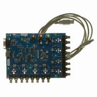
CDB3318
Description
Eval Bd - 8-channel Digital Vol Cntrl
Manufacturer
Cirrus Logic Inc
Specifications of CDB3318
Main Purpose
Audio, Volume Control
Embedded
No
Utilized Ic / Part
CS3318
Primary Attributes
8 Single-Ended Analog Inputs and Outputs, USB or RS232 Interface
Secondary Attributes
Graphical User Interface
Description/function
Audio DSPs
Operating Supply Voltage
8 V to 9 V
Product
Audio Modules
Lead Free Status / RoHS Status
Contains lead / RoHS non-compliant
For Use With/related Products
CS3310
Lead Free Status / RoHS Status
Contains lead / RoHS non-compliant, Contains lead / RoHS non-compliant
Other names
598-1497


14
5. APPLICATIONS
5.1
5.2
5.2.1
General Description
The CS3318 is an 8-channel digitally controlled analog volume control designed for audio systems. It incor-
porates a total adjustable range of 118 dB in ¼ dB steps, spread evenly over 96 dB of attenuation and
22 dB of gain.
The internal analog architecture includes one op-amp per channel, each with an input resistor network for
attenuation and a feedback resistor network for gain. Analog switch arrays are used to select taps in the
input and feedback resistor networks, thereby setting the gain or attenuation of each channel. These switch
arrays are controlled via the digital control port, bridging the gap between the analog and digital domains.
Figure 4 on page 13
The CS3318 incorporates highly configurable zero-crossing detection for glitch-free volume level changes.
Volume changes may be configured to occur immediately or on a signal zero-crossing. In the event that the
signal does not cross zero, the CS3318 provides 8 selectable time-out periods in the range of 5 ms to 50 ms
after which the volume level will be changed immediately. When the CS3318 receives more than one vol-
ume change command before a zero-crossing or a time-out, the CS3318 is able to implement the previous
volume change command immediately or discard it and act only on the most recent command. The
Crossing Detection” section on page 22
tection functionality and controls.
The CS3318 includes a comprehensive I²C/SPI serial control port interface for volume changes and device
configuration. This interface provides for easy system integration of up to 128 CS3318 devices over a single
2-wire I²C or 3-wire SPI bus, allowing many channels of volume control with minimal system controller I/O
requirements. Devices may be addressed on an individual and grouped basis, simplifying simultaneous
configuration of a group of channels across multiple devices, while allowing discrete control over all chan-
nels on an individual basis. The
tailed description of the serial control port features and functionality.
System Design
Very few external components are required to support the CS3318. Typical power supply decoupling com-
ponents are the only external requirements, as shown in
Analog Inputs
No external circuitry is required to interface between the audio source and the CS3318’s inputs. However,
as with any adjustable gain stage, the affects of a DC offset at the input must be considered. Capacitively
coupling the analog inputs may be required to prevent “clicks and pops” which occur with gain changes if
an appreciable offset is present.
The addition of an input coupling capacitor will form a high-pass filter with the CS3318’s input impedance.
Given nominal values of input impedance and coupling capacitor, a 10 µF coupling capacitor will result in
less than 0.03 dB of attenuation at 20 Hz. If additional low-frequency attenuation can be tolerated, a small-
er coupling capacitor may be used.
The CS3318 requires a low source impedance to achieve maximum performance, and a source-imped-
ance of 600 Ω or less is recommended.
The maximum input level is limited by the input signal swing capability of the internal op-amp. Signals ap-
proaching the analog supply voltages may be applied to the analog input pins if the internal attenuator
limits the output signal to within
provides a detailed diagram of the CS3318’s internal architecture.
“System Serial Control Configuration” section on page 23
1.35 V
provides a detailed description of the CS3318’s zero-crossing de-
of the analog supply rails.
Figure 3 on page
12.
provides a de-
CS3318
DS693F1
“Zero-
Related parts for CDB3318
Image
Part Number
Description
Manufacturer
Datasheet
Request
R

Part Number:
Description:
Development Kit
Manufacturer:
Cirrus Logic Inc
Datasheet:
Part Number:
Description:
Development Kit
Manufacturer:
Cirrus Logic Inc
Datasheet:


Part Number:
Description:
High-efficiency PFC + Fluorescent Lamp Driver Reference Design
Manufacturer:
Cirrus Logic Inc
Datasheet:
Part Number:
Description:
Development Kit
Manufacturer:
Cirrus Logic Inc
Datasheet:
Part Number:
Description:
Development Kit
Manufacturer:
Cirrus Logic Inc
Datasheet:

Part Number:
Description:
Development Kit
Manufacturer:
Cirrus Logic Inc
Datasheet:
Part Number:
Description:
Development Kit
Manufacturer:
Cirrus Logic Inc
Datasheet:
Part Number:
Description:
Development Kit
Manufacturer:
Cirrus Logic Inc
Datasheet:
Part Number:
Description:
Development Kit
Manufacturer:
Cirrus Logic Inc
Datasheet:

Part Number:
Description:
EVALUATION BOARD FOR CS8427
Manufacturer:
Cirrus Logic Inc
Datasheet:

Part Number:
Description:
BOARD EVAL FOR CS8416 RCVR
Manufacturer:
Cirrus Logic Inc
Datasheet:

Part Number:
Description:
EVALUATION BOARD FOR CS8420
Manufacturer:
Cirrus Logic Inc
Datasheet:

Part Number:
Description:
KIT DEVELOPMENT EP9315 ARM9
Manufacturer:
Cirrus Logic Inc
Datasheet:

Part Number:
Description:
KIT DEVELOPMENT EP9302 ARM9
Manufacturer:
Cirrus Logic Inc
Datasheet: