CDB3318 Cirrus Logic Inc, CDB3318 Datasheet - Page 15
CDB3318
Manufacturer Part Number
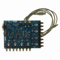
CDB3318
Description
Eval Bd - 8-channel Digital Vol Cntrl
Manufacturer
Cirrus Logic Inc
Specifications of CDB3318
Main Purpose
Audio, Volume Control
Embedded
No
Utilized Ic / Part
CS3318
Primary Attributes
8 Single-Ended Analog Inputs and Outputs, USB or RS232 Interface
Secondary Attributes
Graphical User Interface
Description/function
Audio DSPs
Operating Supply Voltage
8 V to 9 V
Product
Audio Modules
Lead Free Status / RoHS Status
Contains lead / RoHS non-compliant
For Use With/related Products
CS3310
Lead Free Status / RoHS Status
Contains lead / RoHS non-compliant, Contains lead / RoHS non-compliant
Other names
598-1497


DS693F1
5.2.2
5.2.3
5.3
Power-Up and Power-Down
The CS3318 will remain in a completely powered-down state with the control port inaccessible until the RE-
SET pin is brought high. Once RESET is high, the control port will be accessible, but the internal amplifiers
will remain powered-down until the PDN_ALL bit is cleared.
To bring a channel out of power-down, both the PDN_ALL and the channel’s PDNx bit must be cleared. By
default, all channels’ PDNx bits are cleared, and the PDN_ALL bit is set. To minimize audible artifacts during
power-up process, the CS3318 automatically holds each channel’s volume at mute until its amplifier has
completed its power-up sequence. Once the power-up process is complete, each channel’s volume will au-
tomatically be set to the correct level according to the CS3318’s control port settings.
To place a channel in power-down, either the channel’s PDNx bit or the PDN_ALL bit must be set. To min-
imize audible artifacts during the power-down process, the CS3318 automatically places each channel in
mute before the amplifier begins its power-down sequence.
The power-up and power-down muting/volume changes are implemented as dictated by the zero-crossing
detection settings (see
required, the zero-crossing mode should be set to immediate before changing the power-down state of the
device or channel.
Referenced Control
PDN_ALL ............................
PDNx...................................
Analog Outputs
The analog outputs are capable of driving
short-circuit protected to
The minimum output load resistance is
As the load resistance decreases, the potential for increased internal heating and the possibility of dam-
age to the device is introduced. Additionally, the load capacitance should be less than
load capacitance may cause increased distortion, and the potential for instability in the output amplifiers.
If a low-impedance or high-capacitance load must be driven, an external amplifier should be used to iso-
late the outputs of the CS3318.
Recommended Layout, Grounding, and Power Supply Decoupling
As with any high-performance device that contains both analog and digital circuitry, careful attention must
be provided to power supply and grounding arrangements to optimize performance.
shows the recommended power arrangements, with VA+, VA-, and VD connected to clean supplies.
Power supply decoupling capacitors should be placed as near to the CS3318 as possible, with the low
value ceramic capacitor being the nearest. Care should be taken to ensure that there is minimal resis-
tance in the analog ground leads to the device to prevent any changes in the defined gain/attenuation set-
tings. The use of a unified ground plane is recommended for optimal performance and minimal radiated
noise. The CS3318 evaluation board demonstrates the optimum layout and power supply arrangements.
Should the printed circuit board have separate analog and digital regions with independent ground planes,
the CS3318 should reside in the analog region of the board.
Extensive use of ground plane fill on the circuit board will yield large reductions in radiated noise effects.
“Zero-Crossing Detection” on page
Register Location
“Power Down All (Bit 0)” on page 35
“Channel Power - Address 0Dh” on page 35
20
mA.
2
kΩ; a load smaller than
2 kΩ
loads to within
22). If an immediate power-up or power-down is
1.35 V
2 kΩ
of the analog supply rails and are
may cause increased distortion.
Figure 3 on page 12
100
pF. Increased
CS3318
15
Related parts for CDB3318
Image
Part Number
Description
Manufacturer
Datasheet
Request
R

Part Number:
Description:
Development Kit
Manufacturer:
Cirrus Logic Inc
Datasheet:
Part Number:
Description:
Development Kit
Manufacturer:
Cirrus Logic Inc
Datasheet:


Part Number:
Description:
High-efficiency PFC + Fluorescent Lamp Driver Reference Design
Manufacturer:
Cirrus Logic Inc
Datasheet:
Part Number:
Description:
Development Kit
Manufacturer:
Cirrus Logic Inc
Datasheet:
Part Number:
Description:
Development Kit
Manufacturer:
Cirrus Logic Inc
Datasheet:

Part Number:
Description:
Development Kit
Manufacturer:
Cirrus Logic Inc
Datasheet:
Part Number:
Description:
Development Kit
Manufacturer:
Cirrus Logic Inc
Datasheet:
Part Number:
Description:
Development Kit
Manufacturer:
Cirrus Logic Inc
Datasheet:
Part Number:
Description:
Development Kit
Manufacturer:
Cirrus Logic Inc
Datasheet:

Part Number:
Description:
EVALUATION BOARD FOR CS8427
Manufacturer:
Cirrus Logic Inc
Datasheet:

Part Number:
Description:
BOARD EVAL FOR CS8416 RCVR
Manufacturer:
Cirrus Logic Inc
Datasheet:

Part Number:
Description:
EVALUATION BOARD FOR CS8420
Manufacturer:
Cirrus Logic Inc
Datasheet:

Part Number:
Description:
KIT DEVELOPMENT EP9315 ARM9
Manufacturer:
Cirrus Logic Inc
Datasheet:

Part Number:
Description:
KIT DEVELOPMENT EP9302 ARM9
Manufacturer:
Cirrus Logic Inc
Datasheet: