CDB3318 Cirrus Logic Inc, CDB3318 Datasheet - Page 17
CDB3318
Manufacturer Part Number
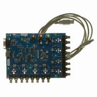
CDB3318
Description
Eval Bd - 8-channel Digital Vol Cntrl
Manufacturer
Cirrus Logic Inc
Specifications of CDB3318
Main Purpose
Audio, Volume Control
Embedded
No
Utilized Ic / Part
CS3318
Primary Attributes
8 Single-Ended Analog Inputs and Outputs, USB or RS232 Interface
Secondary Attributes
Graphical User Interface
Description/function
Audio DSPs
Operating Supply Voltage
8 V to 9 V
Product
Audio Modules
Lead Free Status / RoHS Status
Contains lead / RoHS non-compliant
For Use With/related Products
CS3310
Lead Free Status / RoHS Status
Contains lead / RoHS non-compliant, Contains lead / RoHS non-compliant
Other names
598-1497


DS693F1
5.4
5.4.1
Volume & Muting Control Architecture
The CS3318’s volume and muting control architecture provides the ability to control each channel on an
individual and master basis.
Individual control allows the volume and mute state of a single channel to be changed independently from
all other channels within the device. The CS3318 provides 8 individual volume and muting controls, each
permanently assigned to one channel within the device.
Master control allows the volume and mute state of multiple channels to be changed simultaneously with a
single register write. The CS3318 provides three master controls, and each may be configured to affect any
group of channels within a device.
Refer to the
on page 21
Control Mapping Matrix
Figure 5
that the individual channel controls are fixed to their respective channel, and the master controls may be
configured to affect any or all channels within the device.
Each master control has a corresponding Master X Mask register which allows the user to select which
channels are affected by the control. By default, each master control is configured to affect all channels
within the device. Referring to
broken by setting or clearing its corresponding bit in the control’s Master X Mask register.
The contents of the Master X Mask registers determine which channels are affected by both a master con-
trol’s volume and mute settings. Refer to the
page 18
for a complete diagram of the CS3318’s volume and muting control architecture.
shows a conceptual drawing of the CS3318’s internal control-to-channel mapping matrix. Notice
for an in-depth description of the operation of the available controls.
“Volume Controls” section beginning on page 19
Volume & Muting
Gain/Attenuation
Channel 1
Channel 2
Channel 3
Channel 4
Channel 5
Channel 6
Channel 7
Channel 8
Controls
Master 1
Master 2
Master 3
Analog
Stages
Figure 5
Figure 5. CS3318 Control Mapping Matrix
Fixed Connection
Ch. 1
below, each configurable connection shown may be made and
Ch. 2
“Volume & Muting Control Implementation” section on
Ch. 3
Control Mapping Matrix
Configurable Connection
Ch. 4
and the
Ch. 5
Ch. 6
“Muting Controls” section beginning
Ch. 7
Ch. 8
CS3318
17
Related parts for CDB3318
Image
Part Number
Description
Manufacturer
Datasheet
Request
R

Part Number:
Description:
Development Kit
Manufacturer:
Cirrus Logic Inc
Datasheet:
Part Number:
Description:
Development Kit
Manufacturer:
Cirrus Logic Inc
Datasheet:


Part Number:
Description:
High-efficiency PFC + Fluorescent Lamp Driver Reference Design
Manufacturer:
Cirrus Logic Inc
Datasheet:
Part Number:
Description:
Development Kit
Manufacturer:
Cirrus Logic Inc
Datasheet:
Part Number:
Description:
Development Kit
Manufacturer:
Cirrus Logic Inc
Datasheet:

Part Number:
Description:
Development Kit
Manufacturer:
Cirrus Logic Inc
Datasheet:
Part Number:
Description:
Development Kit
Manufacturer:
Cirrus Logic Inc
Datasheet:
Part Number:
Description:
Development Kit
Manufacturer:
Cirrus Logic Inc
Datasheet:
Part Number:
Description:
Development Kit
Manufacturer:
Cirrus Logic Inc
Datasheet:

Part Number:
Description:
EVALUATION BOARD FOR CS8427
Manufacturer:
Cirrus Logic Inc
Datasheet:

Part Number:
Description:
BOARD EVAL FOR CS8416 RCVR
Manufacturer:
Cirrus Logic Inc
Datasheet:

Part Number:
Description:
EVALUATION BOARD FOR CS8420
Manufacturer:
Cirrus Logic Inc
Datasheet:

Part Number:
Description:
KIT DEVELOPMENT EP9315 ARM9
Manufacturer:
Cirrus Logic Inc
Datasheet:

Part Number:
Description:
KIT DEVELOPMENT EP9302 ARM9
Manufacturer:
Cirrus Logic Inc
Datasheet: