CDB3318 Cirrus Logic Inc, CDB3318 Datasheet - Page 24
CDB3318
Manufacturer Part Number
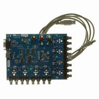
CDB3318
Description
Eval Bd - 8-channel Digital Vol Cntrl
Manufacturer
Cirrus Logic Inc
Specifications of CDB3318
Main Purpose
Audio, Volume Control
Embedded
No
Utilized Ic / Part
CS3318
Primary Attributes
8 Single-Ended Analog Inputs and Outputs, USB or RS232 Interface
Secondary Attributes
Graphical User Interface
Description/function
Audio DSPs
Operating Supply Voltage
8 V to 9 V
Product
Audio Modules
Lead Free Status / RoHS Status
Contains lead / RoHS non-compliant
For Use With/related Products
CS3310
Lead Free Status / RoHS Status
Contains lead / RoHS non-compliant, Contains lead / RoHS non-compliant
Other names
598-1497


24
5.8.2
5.8.2.1
Up to 128 CS3318’s sharing the same CS signal may be connected to a common SPI serial control bus.
This shared serial bus is used to assign a unique device address to each device on the bus such that they
may be independently addressed. To implement this method of device address configuration, the devices
must be connected as shown in
Note that the serial control signals CCLK, CS, and MOSI are connected in parallel to each CS3318. The
active low reset output of the system controller is connected to the RESET input of the first CS3318 in the
chain. The ENOut of the first device is connected to the RESET input of the second CS3318 whose ENOut
signal is connected to the third CS3318. This pattern of connecting the ENOut of device N to the RESET
Serial Control within a Multiple-CS3318 System
The CS3318 allows both independent and simultaneous control of up to 128 devices on a shared I²C or
SPI serial control bus. The address of each device is configured by the host controller via the shared serial
control bus. All serial communication, including the configuration of each device’s address, adheres to a
standard I²C or SPI bus protocol.
A device’s Individual device address, which provides read and write access to the device’s internal regis-
ters, should be set to a unique value, different from all other addresses recognized by devices on the serial
communication bus. This address facilitates independent control of each CS3318 on the serial control
bus.
A device’s Group 1 and Group 2 addresses, which provide write-only access to the device’s internal reg-
isters, may be set to the same value across multiple CS3318’s on the shared serial communication bus.
Assigning common Group addresses to multiple devices in a system allows system sub-master and sys-
tem master volume control. For instance, a system containing 8 CS3318’s may configure the Group 1 ad-
dress of the first set of 4 CS3318’s to 10h, the Group 1 address of the second set of 4 CS3318’s to 20h,
and the Group 2 address of all 8 CS3318’s to A0h. In this manner, a serial control data write to address
10h would act as a system sub-master control to the first set of 4 devices, a write to 20h would act as a
system sub-master control to the second set of 4 devices, and a write to A0h would act as a system mas-
ter control to all devices.
By default, the CS3318 will not respond to serial communication when addressed with its Group 1 or
Group 2 address. The CS3318 will only respond to one or both of these addresses if the corresponding
address has been enabled via the control port. To enable a Group address, its corresponding Enable bit,
located in the LSB of its respective Group address register, must be set.
The CS3318 implements an ENOut signal to facilitate the device address configuration process. This sig-
nal is used to hold all but one un-configured device in a reset state. After the Individual device address of
each device has been set, the ENOut signal is used to enable the “next” device in the chain, allowing its
Individual device address to be set. See
“I²C Mode Control Configuration” on page 26
communication mode.
μC
MOSI
CCLK
RST
SPI Mode Serial Control Configuration
CS
RESET
Figure 9. SPI Serial Control Connections
CS
Device 1
MOSI
Figure
CCLK
ENout
9.
“SPI Mode Serial Control Configuration” section on page 24
RESET
for more information about system configuration in each
CS
Device 2
MOSI
CCLK
ENout
RESET
CS
Device 3
MOSI
CCLK
ENout
CS3318
DS693F1
and
Related parts for CDB3318
Image
Part Number
Description
Manufacturer
Datasheet
Request
R

Part Number:
Description:
Development Kit
Manufacturer:
Cirrus Logic Inc
Datasheet:
Part Number:
Description:
Development Kit
Manufacturer:
Cirrus Logic Inc
Datasheet:


Part Number:
Description:
High-efficiency PFC + Fluorescent Lamp Driver Reference Design
Manufacturer:
Cirrus Logic Inc
Datasheet:
Part Number:
Description:
Development Kit
Manufacturer:
Cirrus Logic Inc
Datasheet:
Part Number:
Description:
Development Kit
Manufacturer:
Cirrus Logic Inc
Datasheet:

Part Number:
Description:
Development Kit
Manufacturer:
Cirrus Logic Inc
Datasheet:
Part Number:
Description:
Development Kit
Manufacturer:
Cirrus Logic Inc
Datasheet:
Part Number:
Description:
Development Kit
Manufacturer:
Cirrus Logic Inc
Datasheet:
Part Number:
Description:
Development Kit
Manufacturer:
Cirrus Logic Inc
Datasheet:

Part Number:
Description:
EVALUATION BOARD FOR CS8427
Manufacturer:
Cirrus Logic Inc
Datasheet:

Part Number:
Description:
BOARD EVAL FOR CS8416 RCVR
Manufacturer:
Cirrus Logic Inc
Datasheet:

Part Number:
Description:
EVALUATION BOARD FOR CS8420
Manufacturer:
Cirrus Logic Inc
Datasheet:

Part Number:
Description:
KIT DEVELOPMENT EP9315 ARM9
Manufacturer:
Cirrus Logic Inc
Datasheet:

Part Number:
Description:
KIT DEVELOPMENT EP9302 ARM9
Manufacturer:
Cirrus Logic Inc
Datasheet: